operation-cp45.pdf - 第168页
Samsung Component Placer CP-45F(V)/FS Operations Manual 11-14 Rectangle: Rectangular shape fiducial mark. Rectangle2: Overlapping of 2 rectangular fiducial marks. Triangle: Triangular shape fiducial mark. Cross: Cross sh…
PCB Edit Command
11-13
<5. Mark List> group
A list of fiducial mark shape data.
<No> column
A serial number of fiducial mark shape
<Name> column
The name of the fiducial mark(Up to 10 characters)
<Shape> column
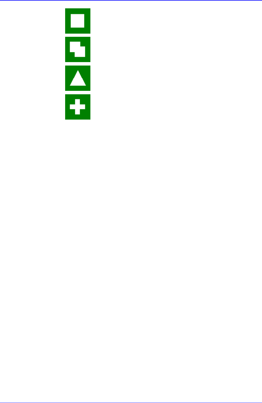
Select the shape of fiducial mark. Available shapes are as follows.
Circle: Circular shape fiducial mark.
Diamond: Diamond shape fiducial mark.
On Fiducial Marks
A fiducial mark has to satisfy several shape and material conditions. During
the design of PCB, the following precautions should be taken.
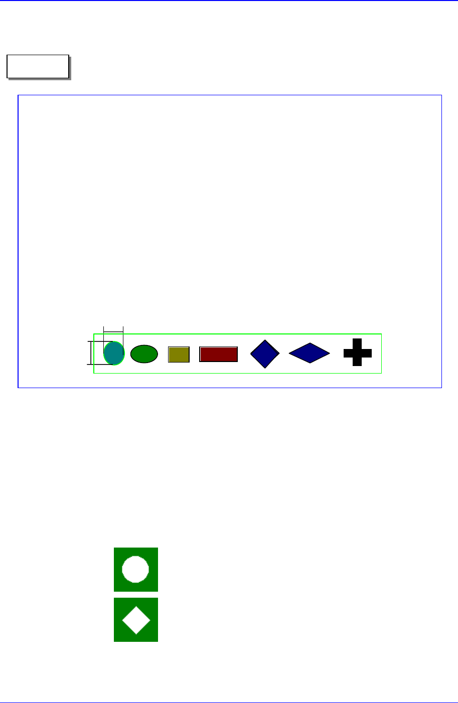
Seven patterns of fiducial mark shapes are possible as shown in the figure
below (top/bottom symmetry or right/left symmetry)
For the size of A, over 2.0 ㎜ is recommended. The width of mark senso
r
beam is about ø0.7 ㎜ measured from the surface of PCB.
Make sure that any changes in color or shape(solder resist, lead pattern)
that can cause error should not be found within 2.0 ㎜ of fiducial mark's
outer edges.
Make sure that the shading difference exits between the fiducial mark and
the board surrounding it.
To ensure search accuracy, coat the surface of the fiducial mark with
copper or lead so that the surface does not reflect. The line shaped fiducial
marks can not be searched with Beam.
A
A
Memo
Samsung Component Placer CP-45F(V)/FS Operations Manual
11-14
Rectangle: Rectangular shape fiducial mark.
Rectangle2: Overlapping of 2 rectangular fiducial marks.
Triangle: Triangular shape fiducial mark.
Cross: Cross shape fiducial mark.
<Camera> column
Select a camera to inspect the fiducial mark. At present, it is fixed to “Move
Camera”.
<6. Form Data> group
Data on the shapes of fiducial marks.
<Size X> edit box
Set the size of fiducial mark in X direction.(Based on the equipment
coordinate system)
<Size Y> edit box
Set the size of fiducial mark in Y direction.(Based on the equipment
coordinate system)
<Arm> edit box
Set the width of the bar of cross shape fiducial marks.
<Polarity> combo box
Select the color of fiducial mark. Available colors are as follows.
White: the mark looks lighter than the surroundings.
Black: the mark looks darker than the surroundings.
<Thickness> edit box
Set the thickness of the fiducial mark.
The value of 0 denotes a full fiducial mark.
A value other than 0 denotes that value for the thickness of the exterior line.
<Rotation> combo box
Select the rotation angle of fiducial mark. In the case of triangles, the
registered form has the corner facing upward, but there are occasions where
the corner is actually facing sideways. In those cases, select the rotation
angle.
Available rotation angles are as follows.
0: the angle of the mark is 0.
90: the mark is rotated to 90°.

PCB Edit Command
11-15
180: the mark is rotated to 180°.
270: the mark is rotated to 270°.
<7. Search Area> group
Set the area in which to search the fiducial mark. The main purpose of this
feature is to limit the search range for when there are forms similar to the mark
near the mark such that they can interfere with recognition on certain PCBs.
<X> edit box
Set the position to start searching for the fiducial mark in X axis. The center
of the vision monitor screen is 0. In general, it is -3 mm.
<Y> edit box
Set the position to start searching for the fiducial mark in Y axis. The center
of the vision monitor is 0. In general, it is -3 mm.
<Width X> edit box
Set the value of search range in X axis. In general, it is 6 mm.
<Width Y> edit box
Set the value of search range in Y axis. In general, it is 6 mm.
<8. Parameter> group
<Score> edit box
The accuracy with which the fiducial mark matches the given data expressed
in number is “score”. The score ranges from 0 to 100. The value set in
<Score> denotes the minimum “score” to be accepted. In general, it should be
at least 600(default value) for accurate adjustment. Even in the worst case, it
should be over 300.
<Light> group
Set the light value when the fiducial mark is inspected. In general, 7 is
appropriate but it can be adjusted according to the condition of PCB and
fiducial mark.
<Tuning> button