operation-cp45.pdf - 第148页
Samsung Component Placer CP-45F(V)/FS Operations Manual 9-8 Figur e 9-5. “ Manual T ools – Camera ” dialog 9.2. Current Position <Position Window> command displays the current position of each axis and the nam e of…
View Commands
9-7
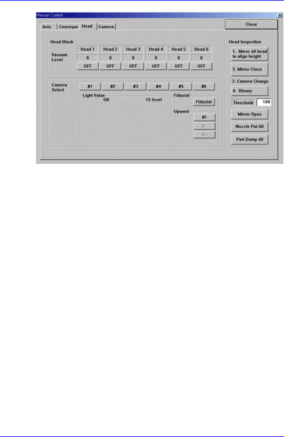
Figure 9-4. “Manual Tools – Head block” dialog box
<Vacuum level> group
Turn on/off the air pressure of each head.
<Camera Select> group
Set the light value of the fiducial camera, fly camera, and upward camera.
<Head Inspection> group
<Move all head to align height> button
Move the Z axis of the head to the Align height to test the head.
<Mirror Open/Close> button
Open or Close the Mirror.
<Real Display/Binary> button
Displays the actual image and the processed image (binary) on the vision
screen.
<Nozzle Put All> button
Puts all Nozzles.
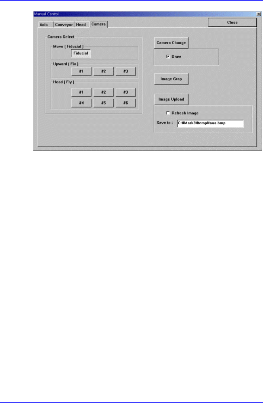
9.1.4. Camera Dialog Box
It tests the status of each camera through the vision monitor according to the image grab
and lighting
Samsung Component Placer CP-45F(V)/FS Operations Manual
9-8
Figure 9-5. “Manual Tools – Camera” dialog
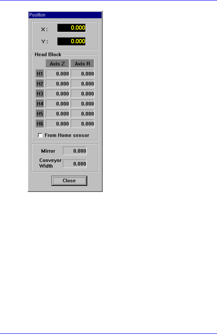
9.2. Current Position
<Position Window> command displays the current position of each axis and the name of
the nozzle installed on the head in real time. When this command is selected, the
following window is displayed on the MMI main screen.
View Commands
9-9
Figure 9-6. “Position” message box
X:
Displays the current position of Head1 in X-direction from the mechanical origin.
Y:
Displays the current position of Head1 in Y-direction from the mechanical origin.
Head Block Group
Head1/Axis Z
Displays the current height of Head1.
Head1/Axis R
Displays the current rotational angle of Head1.
Head2/Axis Z