operation-cp45.pdf - 第217页
PCB Edit Command 1 1-63 <Outline> button Displays the outline of the component on th e vision monitor by using the set align data. <Move…> button Performs component pickups or m oves to the fix camera. …
Samsung Component Placer CP-45F(V)/FS Operations Manual
11-62
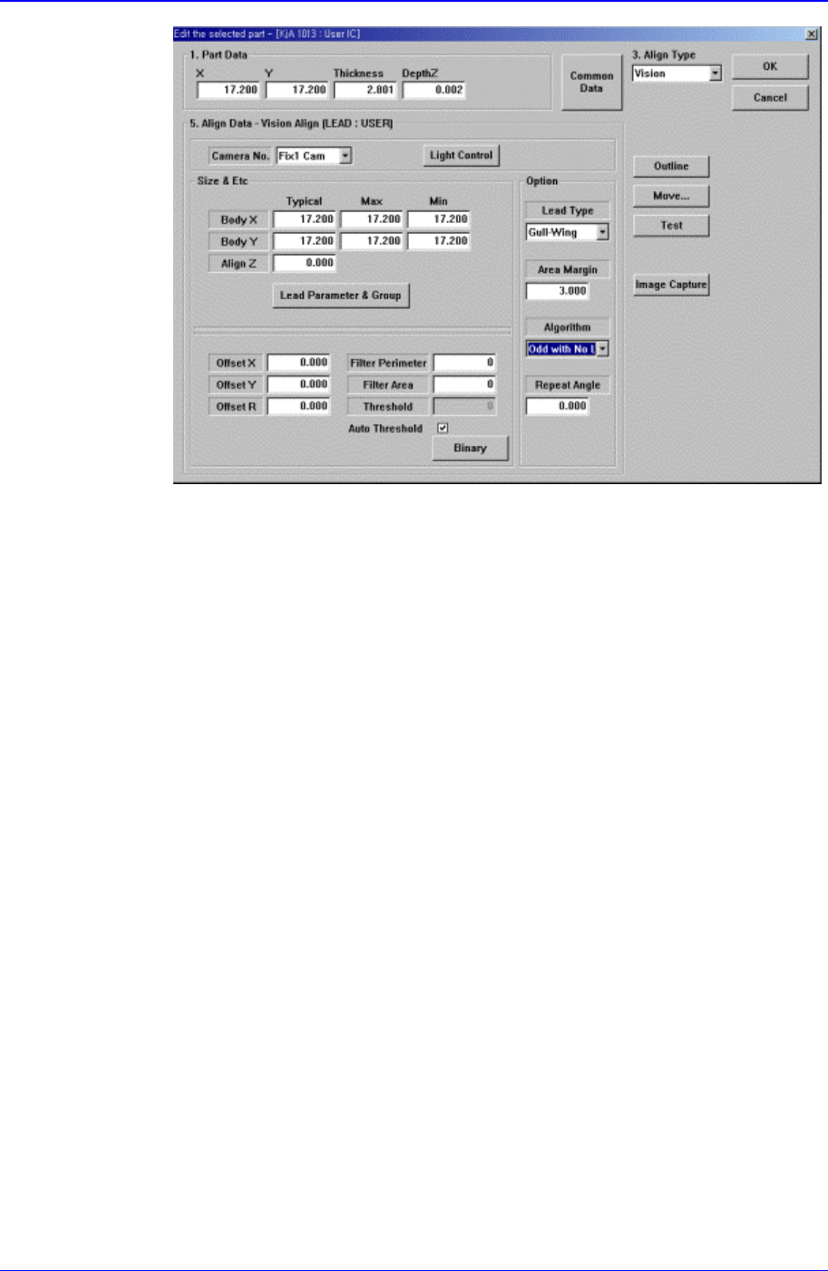
Figure 11-40 “Align Type = Vision, Package Group = User IC, Algorithm = Odd with
Lead” dialog box
<Offset X> edit box
Set the offset value between the component centroid and the actual
component center in X direction.
<Offset Y> edit box
Set the offset value between the component centroid and the actual
component center in Y direction.
<Offset R> edit box
Set the offset value between the angle of the main axis of the component and
the actual angle.
<Filter Perimeter> edit box
Set the value to remove noise in the component vision image. If the
perimeter of the object in the image is smaller than this value, it is processed
as noise.
<Filter Area> edit
Set the value to remove noise in the component vision image. If the area of
the object in the image is smaller than this value, it is processed as noise.
<Threshold> edit box
When there is a pre-treatment process for component recognition and the
gray level image is converted into binary, it is the value used as the criteria to
determine black and white.
The value range is 0 – 255(0: black, 255: white), and this value serves to
differentiate the component from the background. When the set value is 0,
the value is set automatically during component recognition.
<Auto Threshold> check box
Check it to set the <Threshold> value automatically.
PCB Edit Command
11-63
<Outline> button
Displays the outline of the component on the vision monitor by using the set align
data.
<Move…> button
Performs component pickups or moves to the fix camera.
<Test> button
Performs the component recognition test by using the set align data.
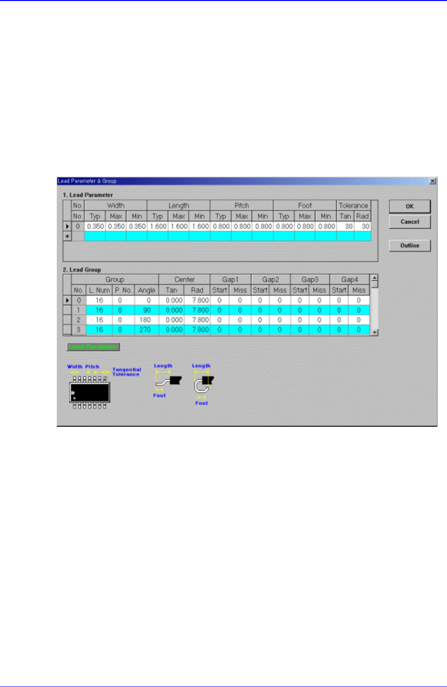
11.1.15.1. Lead Parameter
Set the lead parameter for User ICs. Possible lead parameters are up to 8.
Figure 11-41. Screen showing “Lead Parameter” setting in the dialog box for “User IC Lead
Parameter & Group “
<Lead Parameter> group
Set the lead parameter.
<No.> column
Displays the lead parameter number. Possible range is 0 – 7.
<Width Typ> column
Set the lead width.
<Width Max> column
Set the lead width including the highest tolerance.
<Width Min> column
Set the lead width including the lowest tolerance.
<Length Typ> column
Set the lead length.
<Length Max> column

Samsung Component Placer CP-45F(V)/FS Operations Manual
11-64
Set the lead length including the highest tolerance.
<Length Min> column
Set the lead length including the lowest tolerance.
<Pitch Typ> column
Set the lead pitch, which is the length from the center of the lead to the center of
the adjacent lead.
<Pitch Max> column
Set the lead pitch including the highest tolerance.
<Pitch Min> column
Set the lead pitch including the lowest tolerance.
<Foot Typ> column
Set the length of the lead that touches the surface.
<Foot Max> column
Set the lead foot including the highest tolerance.
<Foot Min> column
Set the lead foot including the lowest tolerance.
<Tolerance Tan> column
Set the allowable tolerance when the lead is bent to the side. Set it as a
percentage of <Lead Pitch>
<Tolerance Rad> column
Set the allowable tolerance for lead length. Set it as a percentage of <Lead
Length>.
<Outline> button
Displays the outline of the component on the vision monitor by using the set align
data.
11.1.15.2. Lead Group
Set the lead group for User IC. Up to 16 lead groups can be set.