CM602all_EJM8AESM_Service Manual.pdf - 第102页
Inspected on Month Date Year Installation Check List (2/4) Document Ver. 1.00 Customer name: Target model: Modular CM602-L Production code: Software Ver. 1. Purpose: Check that there is no problem with M/C operation by c…
Inspected on Month Date Year
Installation Check List (1/4) Document Ver. 1.00
Customer name:
Target model: Modular CM602-L 1 Type A B C
Production code:
2 Type A B C
Software Ver.
M/C Ver. Recognition Ver.
PT Ver.
1. Purpose: Check that there is no problem with M/C operation by checking the following items at the time of installation.
2. Judgment: Circle the "OK" for each column after inspection or adjustment check.
Serial No. Serial No.
No. Checking points
Check result Check result
1 * Remove the packing materials and then the fitting metals. (List check)
2 Check there is no rust or damage to appearance. NG locations: ( )
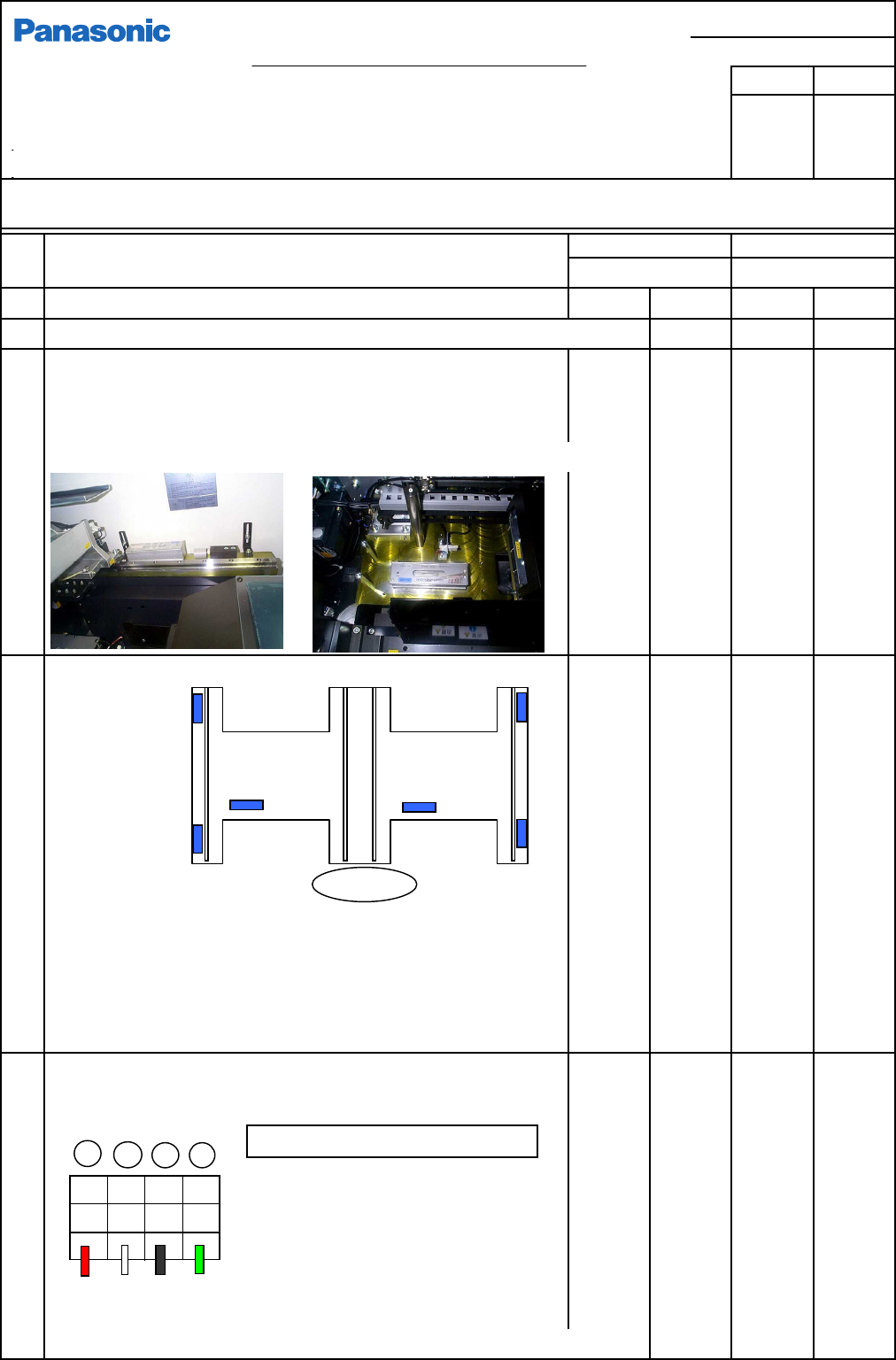
3 Prepare for leveling
* Remove the cover from the Y-axis linear way.
* Clean the leveling surface. (There should be no dirt, burr, etc.)
* Level the M/C so that the same load weight is applied to all four adjusting bolts.
4 Level the machine.
* Standard transport height: Standard 900 to 920 mm
* Record the bubble positions on the separate level check list.
* Once the machine has been leveled, put a mark on the lock nut.
* Check that the six bolts are seated on the floor securely.
5 Power connection (Tightening the power cable terminal.)
* Primary-power connection (Turn off the customer's primary-power.)
• PFSC uses a 4-core AWG#10 cable for
power cable in Japan.
<Power conditions>
Frequency: 50/60 Hz +/- 5%
Rated capacity: 2.5 KVA
* Use the terminal tightening tool that is delivered specially for this purpose.
OK
OK
OK
OK
OK
OK
OK
OK
OK
OK
OK
OK
OK
OK
OK
OK
OK
OK
OK
OK
OK
OK
OK
OK
OK
OK
OK
Installed by
Customer
OK OK
OK
X方向
Terminal block (TB4)
LO1 LO2 LO3 PE
Red Wh. Blk. Grn
R
S
T
E
Tightening torque: 0.8 - 1.6N•m
Y-direction level position
Operator
X-direction level position
Copy for customer
EJM8A-J-SMA020103-A01-00
Panasonic Factory Solutions Co., Ltd.
Page 2-1-3-33
F3A0016-03A
Inspected on Month Date Year
Installation Check List (2/4) Document Ver. 1.00
Customer name:
Target model: Modular CM602-L
Production code:
Software Ver.
1. Purpose: Check that there is no problem with M/C operation by checking the following items at the time of installation.
2. Judgment: Circle the "OK" for each column after inspection or adjustment check.
Serial No. Serial No.
No. Checking points
Check result Check result
5
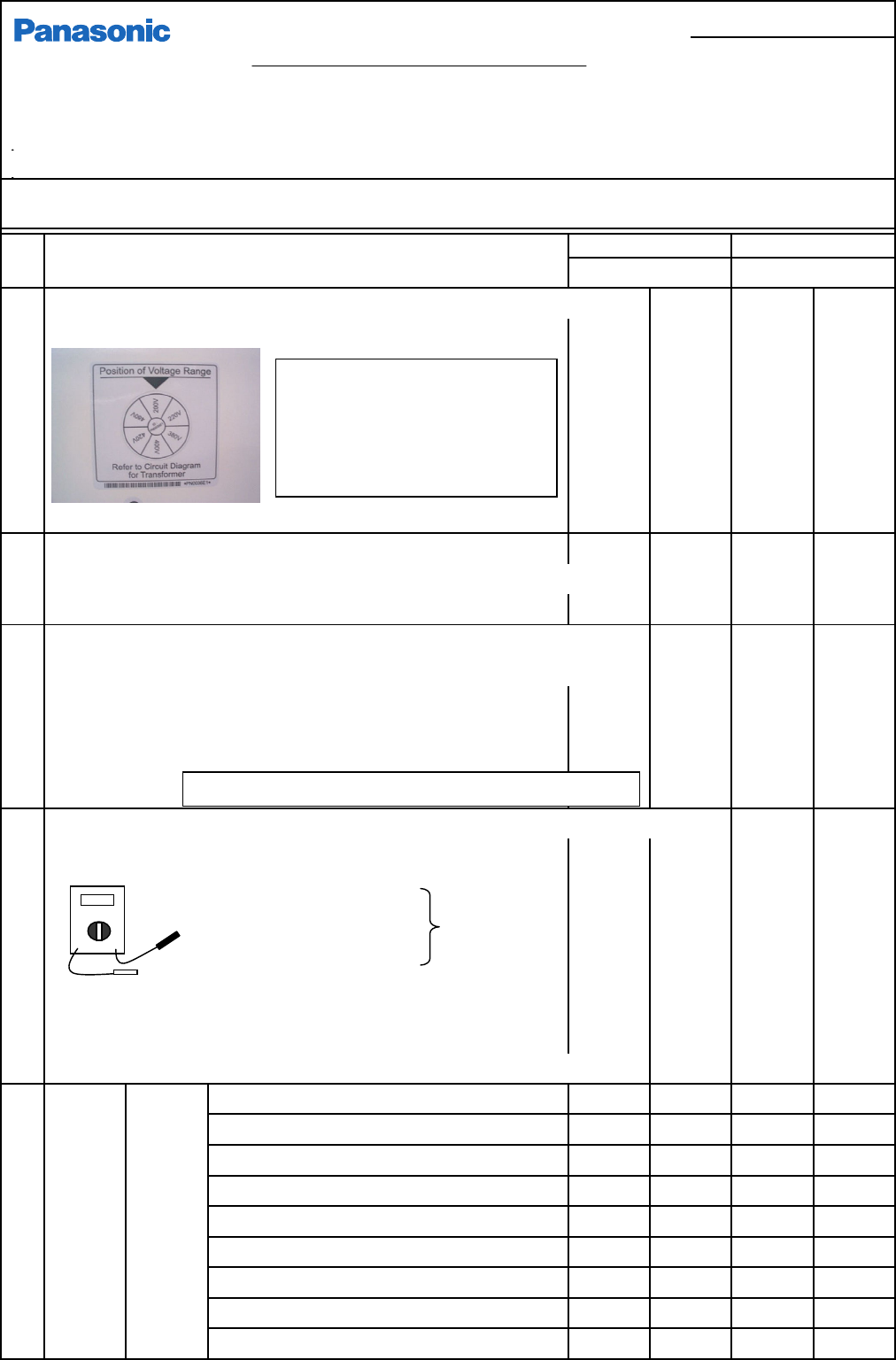
Check the voltage connection label. (Turn off the user's primary power.)
* Check that factory supply voltage is aligned with the q position.
6 Check the 3-level status indicator for secureness.
* Be careful not damage the machine roof, etc. when installing or fixing the indicator in pl
a
* Secure the cable with cable ties.
7
Measure voltage and resistance. (User's primary power: ON, Machine:OFF)
* Visually check the terminal-block ground line (PE) is connected to the factory ground.
* Check that no voltage is applied to the ground with a tester.
PE - Machine frame: 0V
PE - Reference ground, Iron bar: 10 w or less
8
Measure primary voltage.
(M/C power: ON) Circle the supply voltage.
Measure voltage.
L1 - L2
E - L1 E - L2 E - L1 E - L2
L2 - L3
Spec. voltage:
( V) ( V) ( V) ( V)
L3 - L1 +/-10V
E - L13 L1- L2 E - L3 L1- L2
(Red) (Black) ( V) ( V) ( V) ( V)
L2 - L3 L3 - L1 L2 - L3 L3 - L1
* Check powering-up. ( V) ( V) ( V) ( V)
(Check the machine for booting-up and the booting screen is displayed.)
9
Measure DC5V (5.05 - 5.10V)
( V) ( V)
voltage. DC12V Record the measured value.
( V) ( V)
DC12V Record the measured value.
( V) ( V)
P12-A (12.90 - 13.00V)
( V) ( V)
P24-A (24.80 - 25.00)
( V) ( V)
* P24-1 is adjusted with Stage-B power-box RF2 VR.
P12-B (12.90 - 13.00)
( V) ( V)
* P12-1 is adjusted with Stage-B power-box RF2 VR.
P24-B (24.80 - 25.00)
( V) ( V)
Measured
valu
e
Measured
valu
e
Measured
valu
e
Measured
valu
e
Measured
valu
e
Measured
valu
e
Measured
valu
e
Measured
valu
e
Measured
valu
e
Measured
valu
e
Measured
valu
e
OK
OK
OK
OK
OK
OK
OK
OK
CPU box
DC power
unit
OK
Measured
valu
e
Measured
valu
e
Measured
valu
e
OK
OK
OK
OK
OK
OK
OK
OK
OK
OK
OK
OK
OK
OK
OK OK
OK
* Supply voltage: 3 phases: 200, 220, 380, 400, 420, 480V
Check the user's primary power and
voltage and check that the label
position is matched with the supply
voltage.
Check the setting of the machine
transformer.
Signal cables (CN00, 01) should not be connected.
Red
Blk.
□お客様控え
EJM8A-J-SMA020103-A01-00
パナソニックファクトリーソリューションズ株式会社
Page 2-1-3-34
F3A0016-03A
Inspected on Month Date Year
Installation Check List (3/4) Document Ver. 1.00
Customer name:
Target model: Modular CM602-L
Production code:
Software Ver.
1. Purpose: Check that there is no problem with M/C operation by checking the following items at the time of installation.
2. Judgment: Circle the "OK" for each column after inspection or adjustment check.
Serial No. Serial No.
No. Checking points
Check result Check result
9
Measure
* P24-2 is adjusted with Stage-A power-box RF2 VR.
voltage.
RF - IPF (12.02 - 12.10V)
RF - IPR (12.02 - 12.10V)
10 Check the vacuum pump for rotation direction. (Check it is vacuumed.)
* If blow is applied, change the primary-power cable.
11 Check air pressure. (When M/C stops, 0.49MPa - 0.54MPa)
12 Check the air pressure switch is set to 0.45MPa.
13
14 Check the servo switch for function. One for each side: front and rear
15
Check the M/C cover switch. (One for each side, Transfer section, Extension conveyor cover OP)
16 Check the tape-float sensor for detection. (4 locations)
17 Check the width-adjustment interlock for detection.
(2 locations)
18 Check the support change interlock for function. (2 locations)
19
20 Check operation-side change. (F and R)
21 Set the recognition-error-judging value. (Set value: 85%)
22 Check saving to a floppy disk and uploading from it.
23 Check the connection cables (SEMEMA) CN00 and CN01 for connection.
24 Check the HUB power and communication cable for connection. (Option)
25 Check PT communication. (Uploading data from PT to M/C. Saving)
To remove a PT comm. error, upload the network configuration from the M/C parameter FD.
26
Check the vacuum-sensor value for each head. (Check sensor function.)
27
28 Correct the mounting positions. (M/C parameters)
(Specifications: CPK1.33 or more) St A F,R
* Placement verifications Target CPK: 1.5 or more St B F,R
(Range: High-speed: 1005 +/-0.05, 0603: +/-0.05, St A F,R
Multi-purpose QFP +/-0.035) St B F,R
If the CPK value does not satisfy the specifications after mount position
teaching, perform teaching again.
OK
OK
OK
OK
OK
OK
OK
OK
OK
OK
OK
OK
OK
OK
OK
OK
OK
OK
OK
( V)
( V)
OK
OK
OK OK
OK
OK
OK
OK
OK
OK
OK
OK
OK
AR
BF
BR
AF
AR
BF
BR
AF
OK OK
OK
Check the emergency stop switch for function. One for each side: front and rear
Color
-
touch
power
Measured
valu
e
Measured
valu
e
Measured
valu
e
Measured
valu
e
( V)
OK
OK
( V)
OK
OK
No. of times
of teaching
OK
Set "System parameter - Screen output to MC" to "Unuse."
OK
OK
OK
OK
OK
OKCheck the nozzle changer for the recognition-hole positions.
(The fiducial mark should cover 1/3 of the cross line.)
* The pickup sensor values for all nozzles should change on the "Axis Info"
screen every time vacuum is turned ON/OFF on the "Output" screen.
* Vacuum value should not be different largely among nozzles.
ST
CPK X
Y
[Direct]
[Shadow]
Times
Times
[QFP]
X
Y
X
Y
X
Y
Customer's copy
EJM8A-E-SMA020103-A01-00
Panasonic Factory Solutions Co., Ltd.
Page 2-1-3-35
F3A0016-03A