CM602all_EJM8AESM_Service Manual.pdf - 第873页
PCB-Warp-Sensor Unit Option Part and Accessory Replacement Remarks Turn off ( O ) the servo switch. Open the safety cover. * Check that the sensor light comes in the center d of the "2-mm-position" hole. Item M…
PCB-Warp-Sensor Unit
Option Part and Accessory Replacement
Remarks
Close the safet
y
cover.
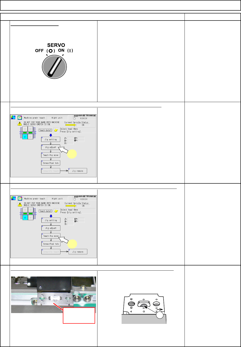
Turn on (I) the servo switch.
Press [UNLOCK] on the operation panel and [Jig adjust] simultaneously.
• The height-measuring jig is clamped.
• The transfer head (sensor) moves to
the "0-mm" position of the height-
measuring jig.
Item
Check that the sensor light comes in the center
c of the "0-mm-position" hole.
9
Press [UNLOCK] on the operation panel and [Teach Pos move] simultaneously.
6
8
7
7
Height-
measuring jig
1
8
EJM8A-E-SMA060505-A01-00
Page 6-5-5-4
PCB-Warp-Sensor Unit
Option Part and Accessory Replacement
Remarks
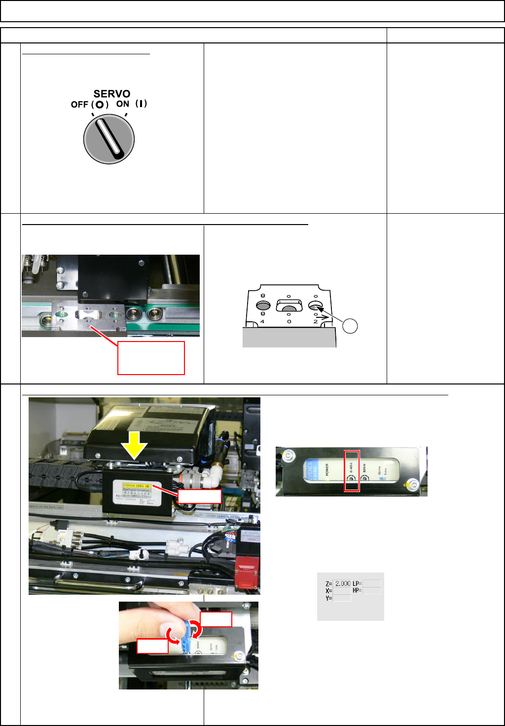
Turn off
(
O
)
the servo switch.
Open the safety cover.
* Check that the sensor light comes in
the center dof the "2-mm-position" hole.
Item
Manually move the transfer head to the "2-mm" position of the jig.
Adjust the height by turning the "0-ADJ" on the upper surface of the amplifier with the special tool.
10
12
11
2
* Adjust the "0-ADJ" until the 'Z' value displayed in
the center of the right half of the screen satisfies
the range of 2.000+/-0.020.
A
m
p
lifie
r
Down
U
p
Height-
measuring jig
EJM8A-E-SMA060505-A01-00
Page 6-5-5-5
PCB-Warp-Sensor Unit
Option Part and Accessory Replacement
Remarks
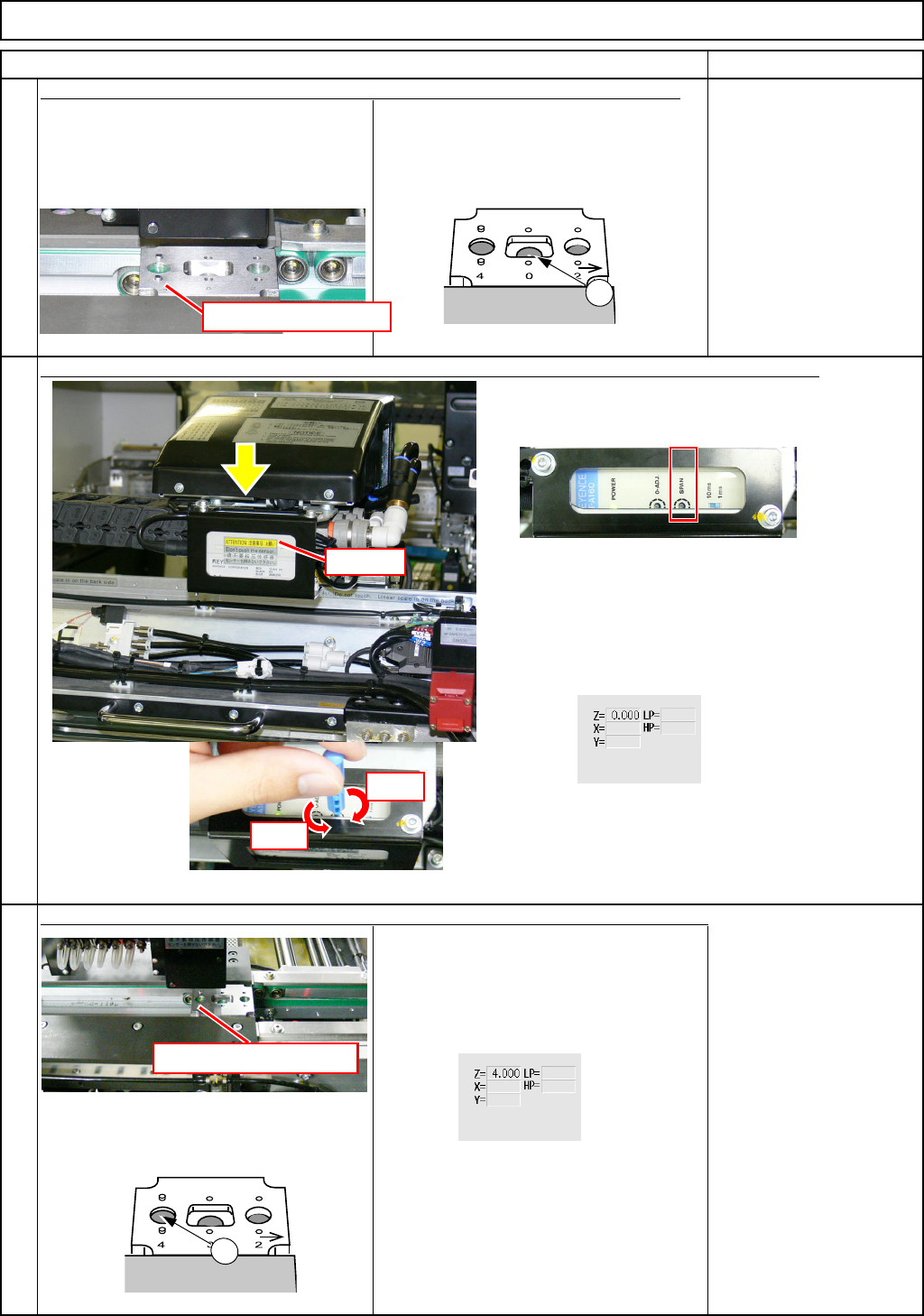
* Check that the sensor light comes in
the center c of the "0-mm-position" hole.
* Check that the sensor light comes in
the center e of the "4-mm-position" hole.
* Check the 'Z' value displayed in the
center of the right half of the screen
satisfies the range of 4.000+/-0.020.
* If the value is outside the range of
4.000 +/- 0.020, repeat Steps 11 to 15.
13
Manually move the transfer head to the "0-mm" position of the height-measuring
14
Item
Manually move the transfer head to the "4-mm" position of the height-measuring jig.
15
Adjust the height by turning the "SPAN" on the upper surface of the amplifier with the special tool.
Height-measuring jig
1
A
m
p
lifie
r
Down
Up
3
* Adjust SPAN until the 'Z' value displayed in the
center of the right half of the screen satisfies the
range of 2.000+/-0.020.
Height-measuring jig
EJM8A-E-SMA060505-A01-00
Page 6-5-5-6