CM602all_EJM8AESM_Service Manual.pdf - 第562页
Machinery Part Replacement Remarks Line Camera Unit Item Connect the LED light connector. Nipper JAE connector Connect the camera connector and the camera power supply connector, which are placed under the board table. P…
Machinery Part Replacement
Remarks
Line Camera Unit
Item
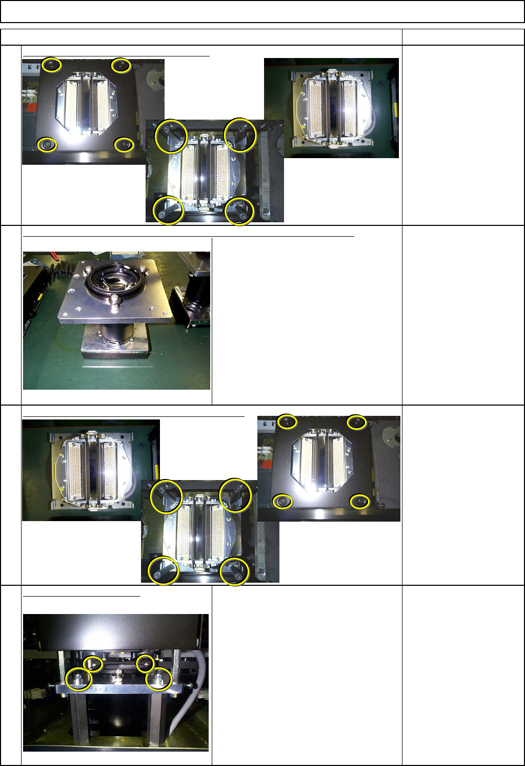
Separate the LED lamp from the camera.
Phillips screwdriver #2
Wrench 10 mm
Screw M4 4 pcs.
Hexagonal spacer 4 pcs.
Check to see that there is no damage to the lens of the new chip camera.
Mount on the LED lamp on the new chip camera.
Phillips screwdriver #2
Wrench 10 mm
Screw M4 4 pcs.
Hexagonal spacer 4 pcs.
Install the camera -LED unit.
Take care with the orientation of the unit. The
cable should be positioned at right when
seen from the front.
Allen key 5 mm
Pipe
Screw M6×20 2 pcs.
Screw M4×12 1 pcs.
9
10
11
12
EJM8A-E-SMA050701-A01-00
Page 5-7-1-4
Machinery Part Replacement
Remarks
Line Camera Unit
Item
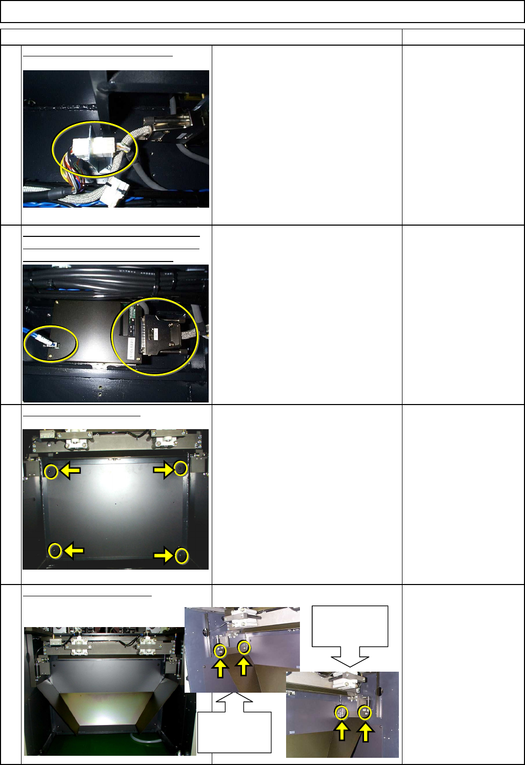
Connect the LED light connector.
Nipper
JAE connector
Connect the camera connector and the
camera power supply connector, which
are placed under the board table.
Put back the lower cover.
Phillips screwdriver #2
Round cross-head screw
M5 4 pcs.
Put the lower chute back on.
Allen key 4 mm
Screw M5x12mm 4 pcs.
Thick washer 4 pcs.
14
13
15
16
Chute installing
section (left)
Chute installing
section (right)
EJM8A-E-SMA050701-A01-00
Page 5-7-1-5
Machinery Part Replacement
Remarks
Line Camera Unit
Item
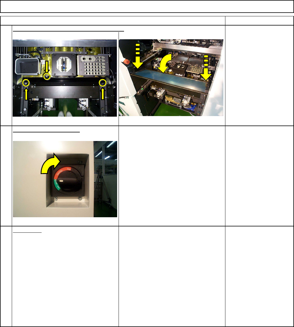
Phillips screwdriver #2
Allen key 3 mm
Screw M4 2 pcs.
Screw M4x10 mm 3 pcs.
Thick washer 3 pcs.
Switch on the main power.
Turn the switch to the right.
For the chip recognition camera and
theta-axis offset teaching, see their
instructions.
A
d
j
ustment
Chip Recognition Camera Theta
Positioning
Teaching
Chip Recognition Camera and Theta-
axis Origin Offset
Mounting Position
Section 4-1-1
Section 4-2-4
Section 4-2-7
Put the feeder cover and the chute back on.
18
19
17
EJM8A-E-SMA050701-A01-00
Page 5-7-1-6