CM602all_EJM8AESM_Service Manual.pdf - 第150页
Maintenance Adjustment Main Body Beam Remarks Item Put the feeder cover and the chute back o Tighten the two screws at both edges of the cover. Close the cover. Phillips screwdriver #2 Allen key 3 mm Screw M4 2 pcs. Scre…
Maintenance Adjustment Main Body Beam
Remarks
Item
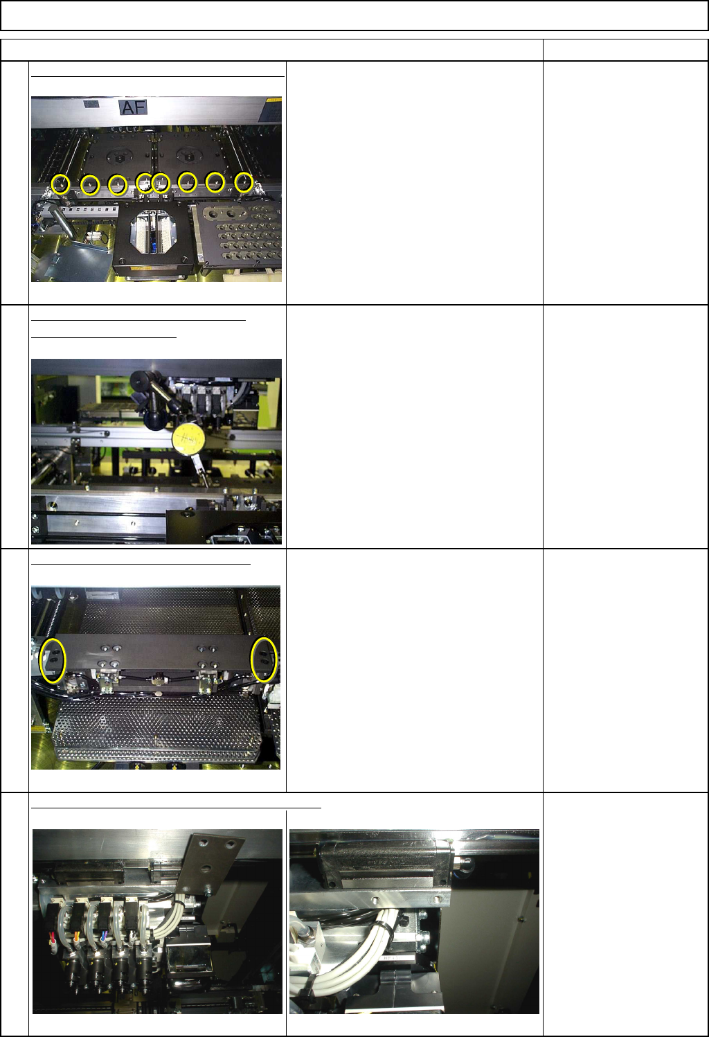
Loosen the screws. Make the rail parallel.
Place the dial gauge at the end of the
reference plate.
Moving it along the plates, level them
with the bolts.
Allen key 3 mm
Specifications:
within ±0.02㎜
Secure the tightness of the screws.
Confirm the parallelism. Specifications:
within ±0.02㎜
Dial gauge
Magnetic stand
Put the fixed Z clamp plate back on.
Allen key 3 mm
M4-10 8 pcs.
Remove the iron plate from the head assembly.
Allen key 3 mm
M4-15 1 pc.
8
5
6
7
EJM8A-E-SMA040104-A01-00
Page 4-1-4-3
Maintenance Adjustment Main Body Beam
Remarks
Item
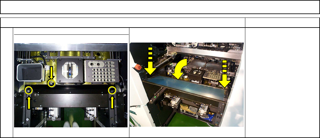
Put the feeder cover and the chute back
o
Tighten the two screws at both edges of
the cover. Close the cover. Phillips screwdriver #2
Allen key 3 mm
Screw M4 2 pcs.
Screw M4x10mm 3 pcs.
Thick washer 3 pcs.
9
EJM8A-E-SMA040104-A01-00
Page 4-1-4-4
Maintenance Adjustment Main Body Beam
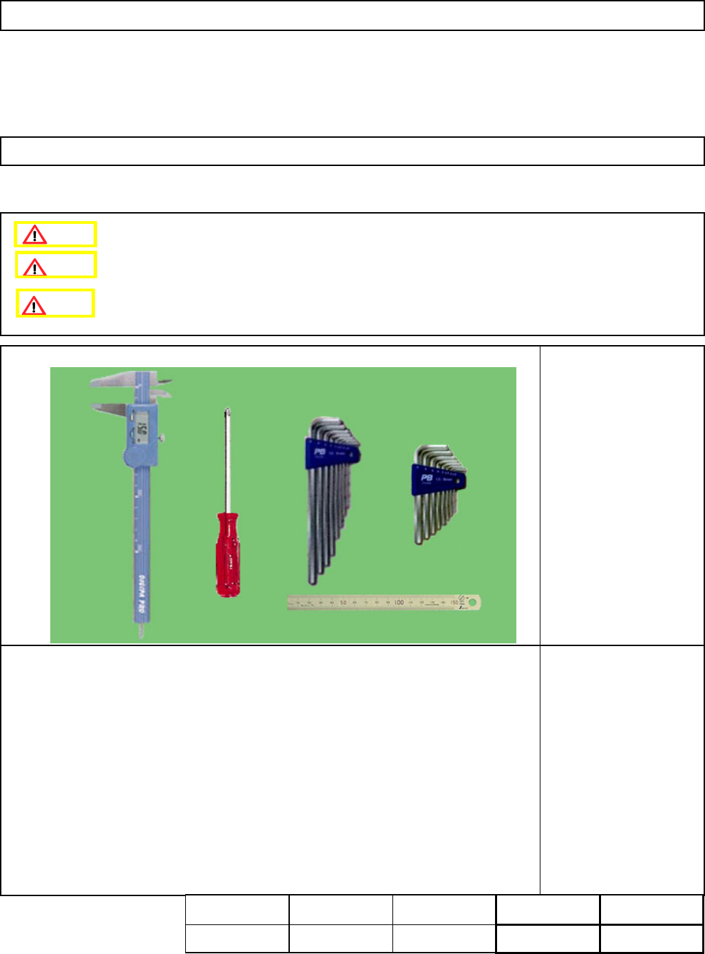
This section describes the procedures for adjusting the board sensor.
・Tools
Phillips screwdriver #2
Allen key 2.5 mm
Ruler 150 mm
Caliper
・Jig
None
Time for replacement:
10 min.
Part Weight: - kgs.
4-1-5 Board Sensor Positioning
Assembly
Adjustment
5min.
Teaching
min.
Total Time Weight of
Part
Removal
Disassembly
5min.
10min.
kgs
Caution
Dange
r
Warning
EJM8A-E-SMA040105-A01-00
Page4-1-5-1