CM602all_EJM8AESM_Service Manual.pdf - 第239页
Maintenance Adjustment Light Transfer-Head Assembly (8 nozzles) This section describes the procedures for teaching the pickup position. Tools None Jig FM-1043 Nozzle Height Teaching Jig Nozzle 120 or 130 4-2-8 Pickup Pos…
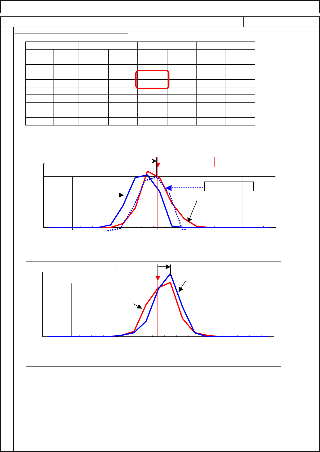
Three types of data (Front, Rear, Front and Rear Total) are shown in the precision data.
The reason that the X-axis Cpk value of Front and Rear Total drops slightly even though the value
of each side (front and rear) is appropriate is that there is a large difference between the maximum
and the minimum of the rear X-axis (Ideal difference: 0). (Opposite sign) See the graphs below:
1
2
3
4
5
6
7
8
9
10
11
12
13
14
15
16
17
18
19
Fig40-2(1) correction
From data
Difference of Min. and Max./2=
(
0.027+0.004
)
/2=0.01
5
(Fig.40-1)
0.015-0.027=-0.012
Enter -0.012 into the rear X-axis mounting position offset so that the Cpk will become similar
to the dotted line on Graph (1) (Correction target).
For the Y-axis: Although the graph is shifted to the negative side by 0.010 (fug40-3(2)), the FY
and the RY are so balanced that the Cpk does not drop.
It is recommended that the front offset be 0 (*); enter the rear offset only.
If the average exceeds 0.005, carry out Adjustment Step 39. In this case, enter an offset.
* Enter "0" into the front offset and adjust with the rear offset so that the Cpk will become the target value.
Maintenance Adjustment Light Transfer-Head Assembly (8 nozzles)
000
-0.060 LESS
000
000
-0.053 ~ -0.059
000000
-0.046 ~ -0.052
000
0000 00
-0.039 ~ -0.045
000000
-0.032 ~ -0.038
316
-0.025 ~ -0.031
010001
-0.018 ~ -0.024
130
49 20 91
-0.011 ~ -0.017
714023737
-0.004 ~ -0.010
19 42 1
12 85 37
0.003 ~ -0.003
39 38 28 37 67 75
0.010 ~ 0.004
44 25 41
1202
0.017 ~ 0.011
15 4 39 3 54 7
0.024 ~ 0.018
3117
000
0.031 ~ 0.025
002020
0.038 ~ 0.032
000
000
0.045 ~ 0.039
000000
0.052 ~ 0.046
000
0
FY軸 RX軸
0.059 ~ 0.053
000000
SX軸
ITEM REMARKS
前側 前後合計
40
Procedures for Entering the Mounting Pos
後側
SY軸
0.060 OVER
0
範囲 FX軸
0000
RY軸
0.050
Tolerance
1959
-0.050
0.050
-0.050
1.330
0.027
-0.021
0.021
-0.018
0.040
0.003
0.008
2.091
FX-axis
2.059
0.020
-0.026
0.019
-0.025
0.044
-0.003
0.008
2.152
FY-axis
Front
1.708
0.032
-0.019
0.027
-0.018
0.046
0.007
0.008
1.976
SX-axis
2.078
0.020
-0.026
0.019
-0.025
0.044
-0.003
0.008
2.213
SY-axis
Front & Rear Total
1.819
0.032
-0.011
0.027
-0.004
0.032
0.010
0.007
2.299
RX-axis
2.124
0.018
-0.026
0.019
-0.021
0.040
-0.004
0.007
2.307
RY-axis
Rear
A
ve+3σ
A
ve-3σ
MAX
MIN
Range
Ave
σ
Cp
Cpk
Item
Fig.38-1
0
10
20
30
40
50
0.060 OVER
0.059 ~
0.053
0.052 ~
0.046
0.045 ~
0.039
0.038 ~
0.032
0.031 ~
0.025
0.024 ~
0.018
0.017 ~
0.011
0.010 ~
0.004
0.003 ~ -
0.003
-0.004 ~ -
0.010
-0.011 ~ -
0.017
-0.018 ~ -
0.024
-0.025 ~ -
0.031
-0.032 ~ -
0.038
-0.039 ~ -
0.045
-0.046 ~ -
0.052
-0.053 ~ -
0.059
-0.060 LESS
X-axis graph
Y-axis graph
0point
FXRX
FY
RY
0point
Correction target
-0.0500.050
-0.050
0.050
Fig.40-2
Fig.40-3
(1)
(2)
EJM8A-E-SMA040207-A01-00
Page 4-2-7-14
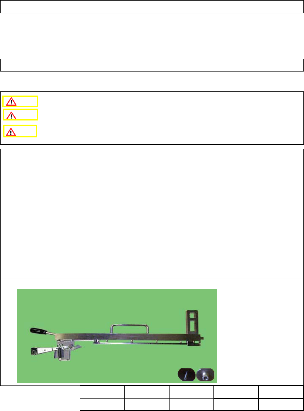
Maintenance Adjustment Light Transfer-Head Assembly (8 nozzles)
This section describes the procedures for teaching the pickup position.
Tools
None
Jig
FM-1043
Nozzle Height Teaching
Jig
Nozzle 120 or 130
4-2-8 Pickup Position
Install the feeder change cart.
Assembly
A
d
j
ustment
min.
Teaching
5min.
Total Time Weight of
Part
Removal
Disassembl
y
min.
5min.
kgs
Caution
Dange
r
Warning
EJM8A-E-SMA040208-A01-00
Page 4-2-8-1
Maintenance Adjustment Light Transfer-Head Assembly (8 nozzles)
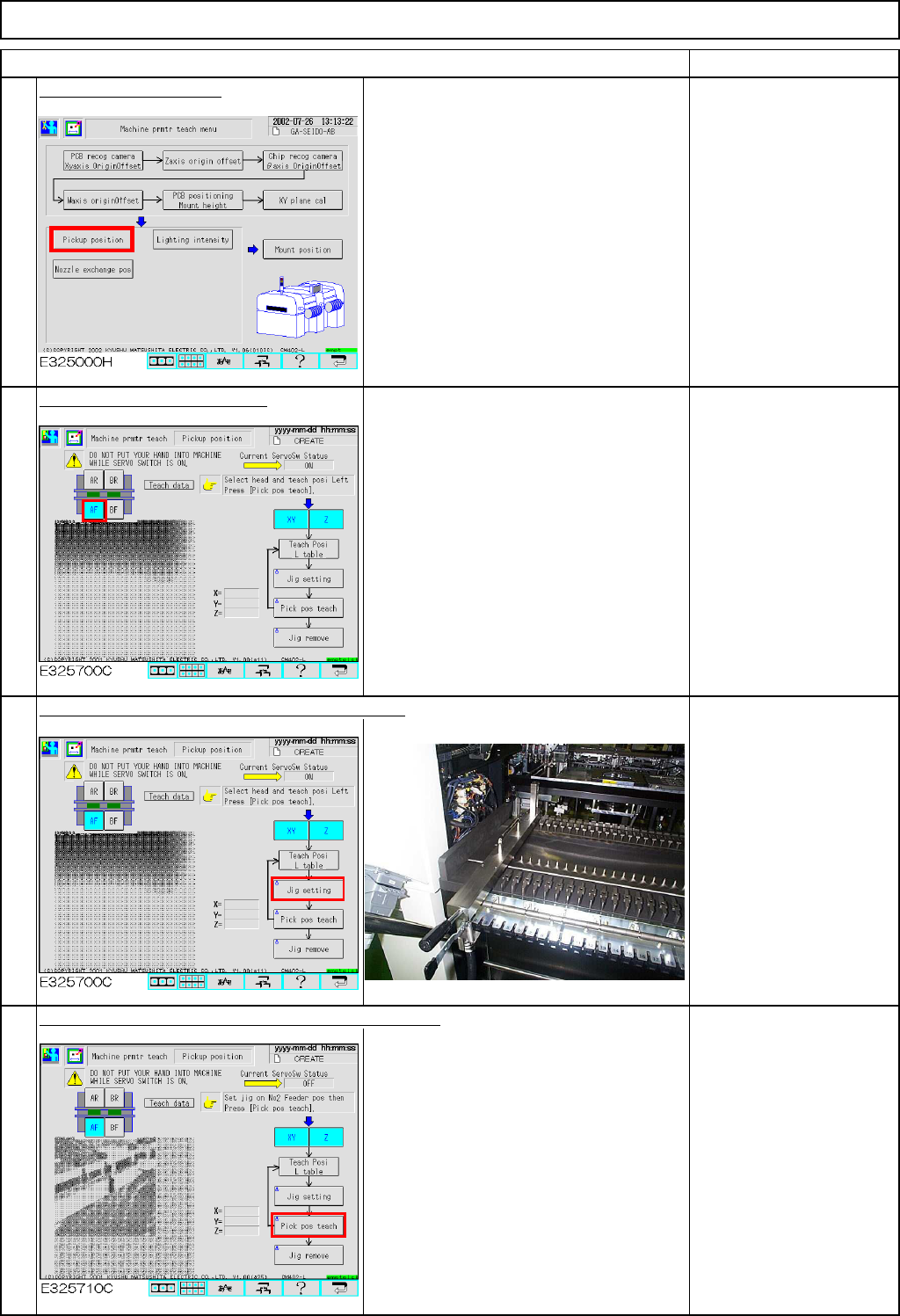
Remarks
Press [Pickup position].
Select the stage to be taught.
Check that:
"XY" and "Z" are selected
(highlighted).
Check that "Check Posi L
table" is selected.
If "Check Posi R table" is
selected, press that key to
change "R" to "L."
Press [Unlock] and [Jig setting] simultaneously.
Place the jig at Position 2
of the feeder table of the
selected stage.
Fit Nozzle 120 or 130 onto
Nozzle position 3.
Press [Unlock] and [Pick pos teach] simultaneously.
The head moves over to the jig.
The head camera recognizes the hole on
the jig so that X and Y of the pickup
position are recognized and corrected.
Nozzle 3 descends to the jig so that Z of
the pickup position is determined.
3
4
1
Item
2
EJM8A-E-SMA040208-A01-00
Page 4-2-8-2