CM602all_EJM8AESM_Service Manual.pdf - 第241页
Maintenance Adjustment Light Transfer-Head Assembly (8 nozzles) Remarks Item Press [Teach Posi L table]. Change "Teach Posi L table" to "Teach Posi R table." If "Teach Posi L table" is selec…
Maintenance Adjustment Light Transfer-Head Assembly (8 nozzles)
Remarks
Press [Pickup position].
Select the stage to be taught.
Check that:
"XY" and "Z" are selected
(highlighted).
Check that "Check Posi L
table" is selected.
If "Check Posi R table" is
selected, press that key to
change "R" to "L."
Press [Unlock] and [Jig setting] simultaneously.
Place the jig at Position 2
of the feeder table of the
selected stage.
Fit Nozzle 120 or 130 onto
Nozzle position 3.
Press [Unlock] and [Pick pos teach] simultaneously.
The head moves over to the jig.
The head camera recognizes the hole on
the jig so that X and Y of the pickup
position are recognized and corrected.
Nozzle 3 descends to the jig so that Z of
the pickup position is determined.
3
4
1
Item
2
EJM8A-E-SMA040208-A01-00
Page 4-2-8-2
Maintenance Adjustment Light Transfer-Head Assembly (8 nozzles)
Remarks
Item
Press [Teach Posi L table].
Change "Teach Posi L table" to "Teach
Posi R table."
If "Teach Posi L table" is
selected, press that key to
change "L" to "R."
Press [Unlock] and [Jig setting] simultaneously.
Place the jig at Position
27 of the feeder table of
the selected stage.
Press [Unlock] and [Pick pos teach] simultaneously.
The head moves over to the jig.
The head camera recognizes the hole on
the jig so that X and Y of the pickup
position are recognized and corrected.
Nozzle 3 descends to the jig so that Z of
the pickup position is determined.
Press [Unlock] and [Jig remove] simultaneously.
The head moves to the nozzle set
position (over the NG box).
Remove the jig and the
nozzle.
5
6
7
8
EJM8A-E-SMA040208-A01-00
Page 4-2-8-3
Maintenance Adjustment Light Transfer-Head Assembly (8 nozzles)
Remarks
Item
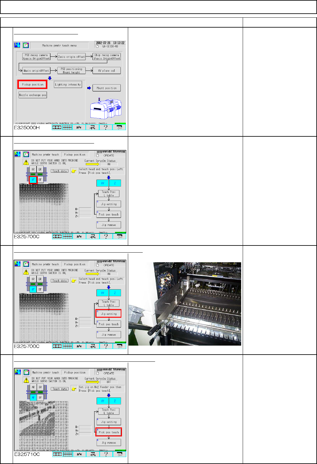
Press the [Return] key.
To save the machine
parameter, press the
[Return] key.
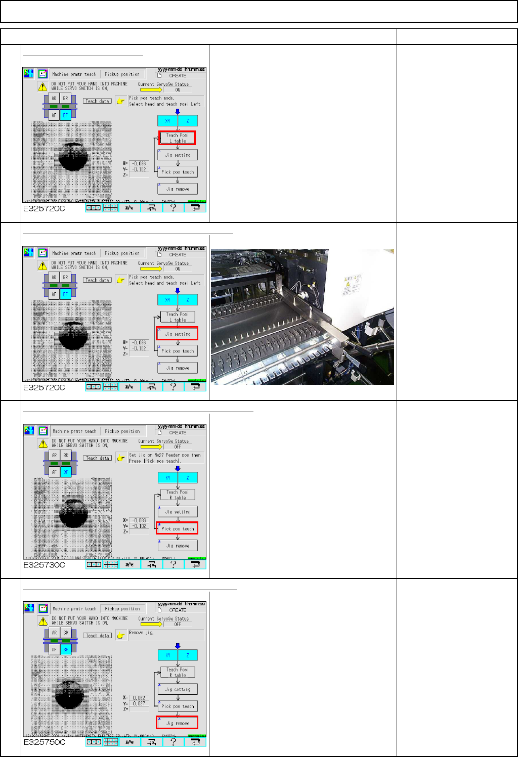
Press [Unlock] and [Run] simultaneously.
All axes of the selected stage return to
the origin.
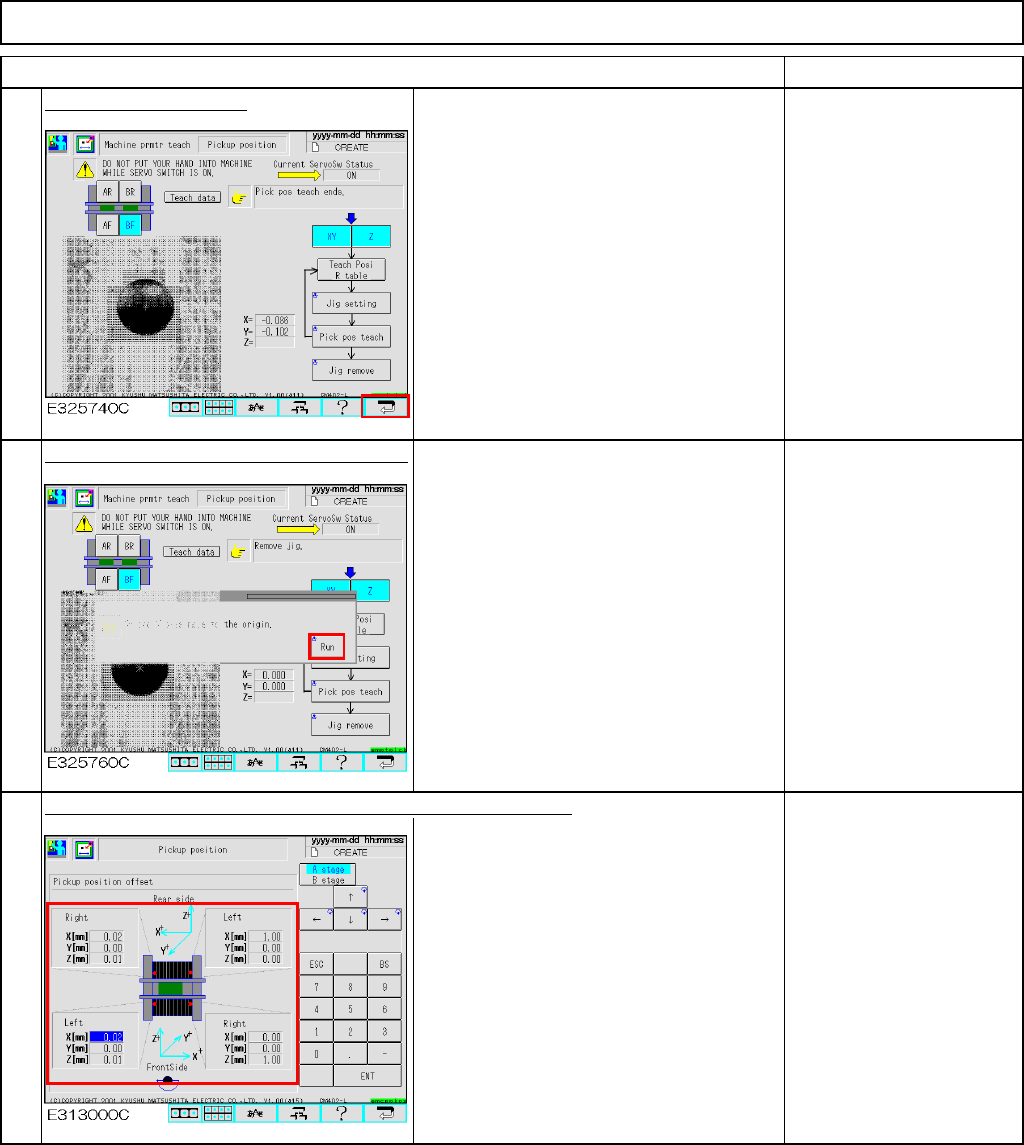
The offsets are entered automatically into the screen below:
Offset range:
X: +/- 1.0 mm
Y: +/- 1.0 mm
Z: +/- 1.0 mm
9
10
11
EJM8A-E-SMA040208-A01-00
Page 4-2-8-4