CM602all_EJM8AESM_Service Manual.pdf - 第958页
Tray 20 Put the cover back on. Phillips screwdriver #2 Screw M4 12 pcs. 19 Teach pickup position. See Section "7-1-2. Shuttle Tray Teaching." 18 Inch the dog by 0.1 mm. Allen key 2.5 mm Screw M3 2 pcs. Precisel…
Tray Shuttle Tray
Item Remarks
15
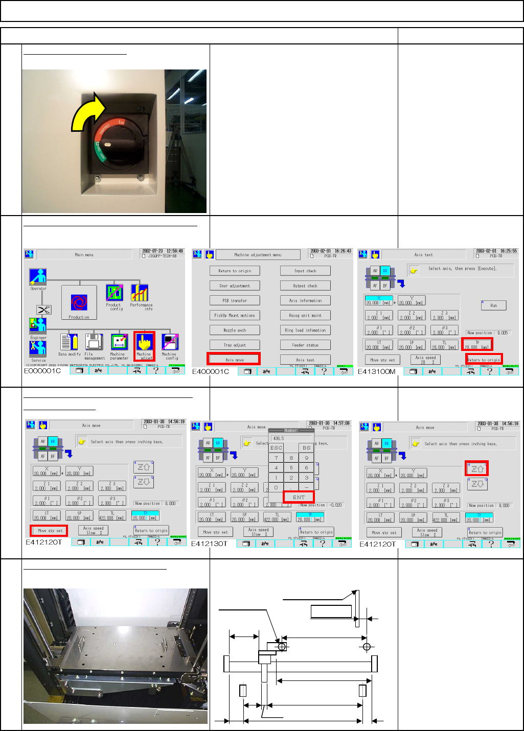
Move the extension axis towards you
Return the extension-axis to the origin.
14
16
Position the bearing with the jig.
Jig: FM-0982
by 436.5 stroke.
13
Power up the machine.
This area should be for
servicemen only because
the cover is open.
A
=436.5st
Origin
E
CD
(454.5)
8
F
B=11.0
Whole shutter
(2)
(73)
436.5
EJM8A-E-SMA070113-A01-00
Page 7-1-13-5
Tray
20
Put the cover back on.
Phillips screwdriver #2
Screw M4 12 pcs.
19
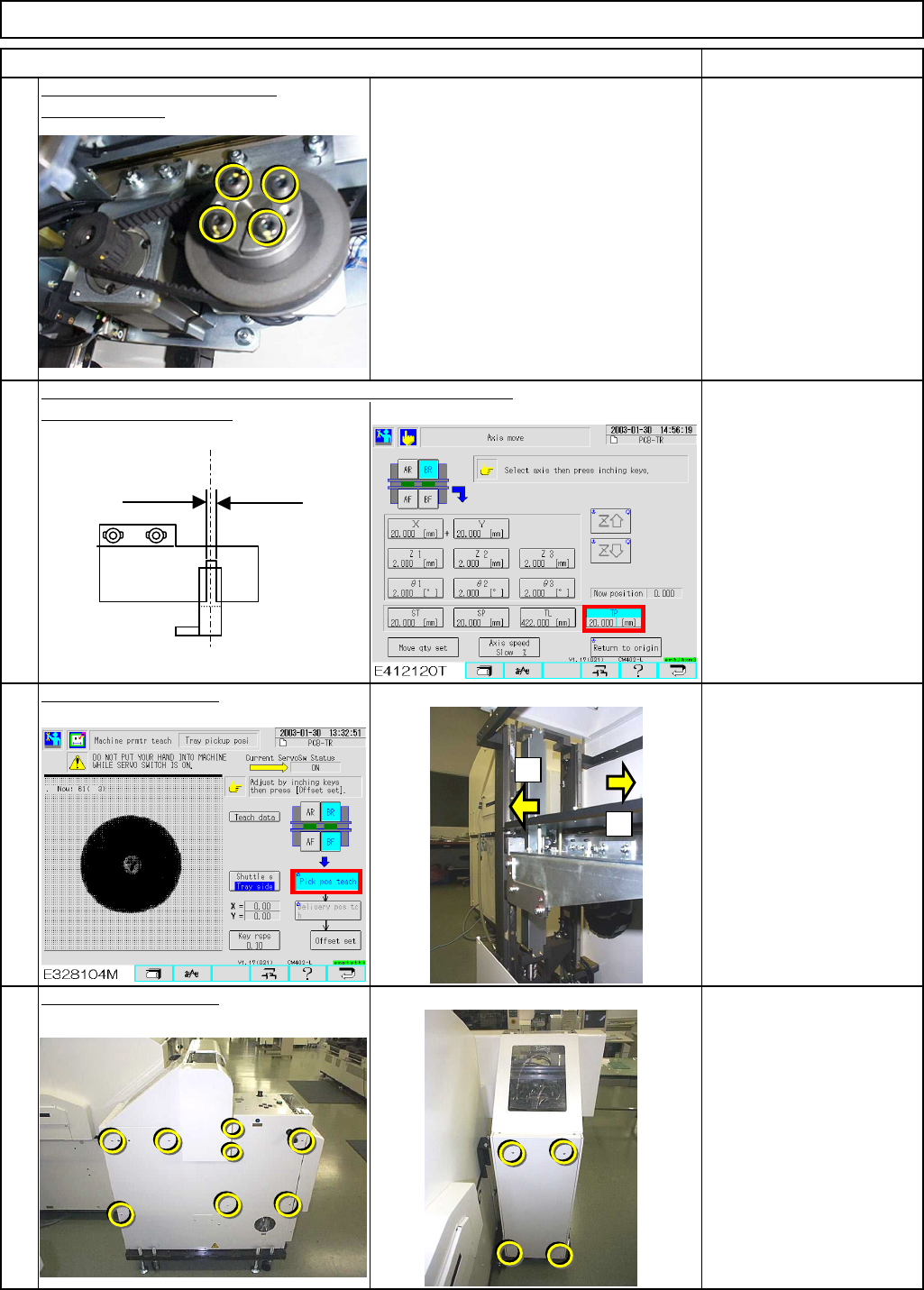
Teach pickup position.
See Section "7-1-2. Shuttle
Tray Teaching."
18
Inch the dog by 0.1 mm.
Allen key 2.5 mm
Screw M3 2 pcs.
Precisely position the slit of the jig at the extension position.
17
Tighten the motor power lock.
Remove the jig.
Allen key 4 mm
Screw M5 4 pcs.
Item Remarks
Shuttle Tray
+
-
Magazine side
(0.5 mm)
Lift side
(1.0 mm)
Light-axis sensor
Extension position
PH sensor
Dog
EJM8A-E-SMA070113-A01-00
Page 7-1-13-6
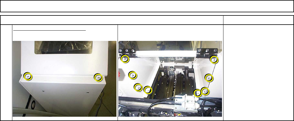
21
Put the upper cover back on.
Phillips screwdriver #2
Allen key 3 mm
Screw M4 2 pcs.
M4 x 10L 8 pcs.
Item Remarks
Tray Shuttle Tray
EJM8A-E-SMA070113-A01-00
Page 7-1-13-7