CM602all_EJM8AESM_Service Manual.pdf - 第159页
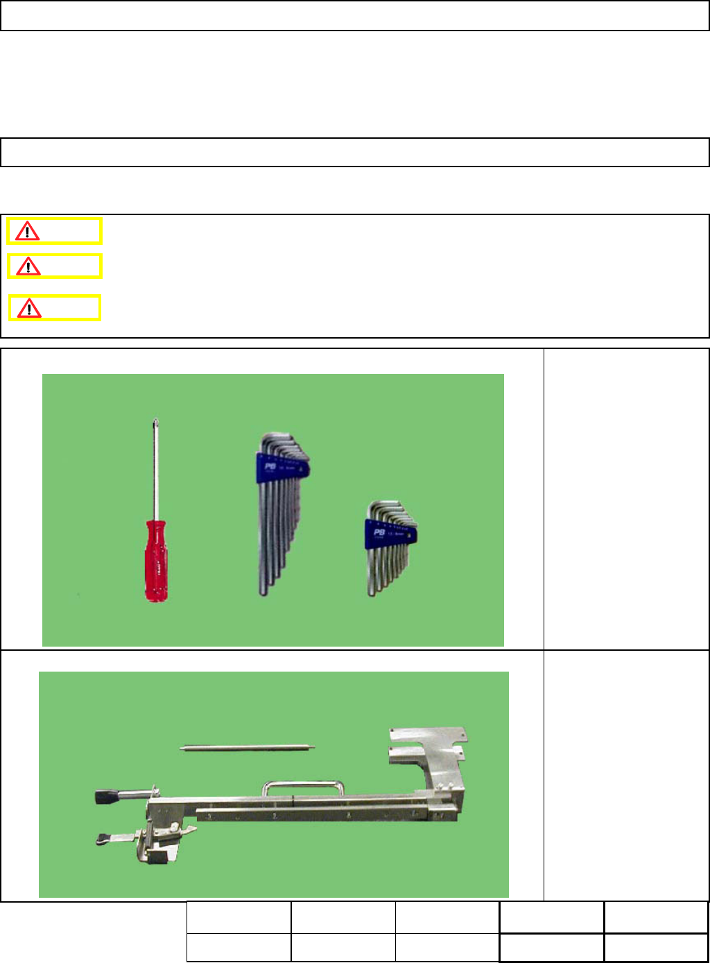
Maintenance Adjustment Main Body Beam ・ Tools Phillips screwdriver #2 Allen key 2.5 mm Tape (opaque) ・ Jig FM-1055 Tape Float Sensor Adjusting jig 4-1-7 Tape Float Sensor Adjustment This section describes the procedures …
Maintenance Adjustment Main Body Beam
Remarks
Item
Allen key 3 mm
Iron plate
Screw M4
See the sections at right.
Section 4-2-5
Section 4-2-7
13
14
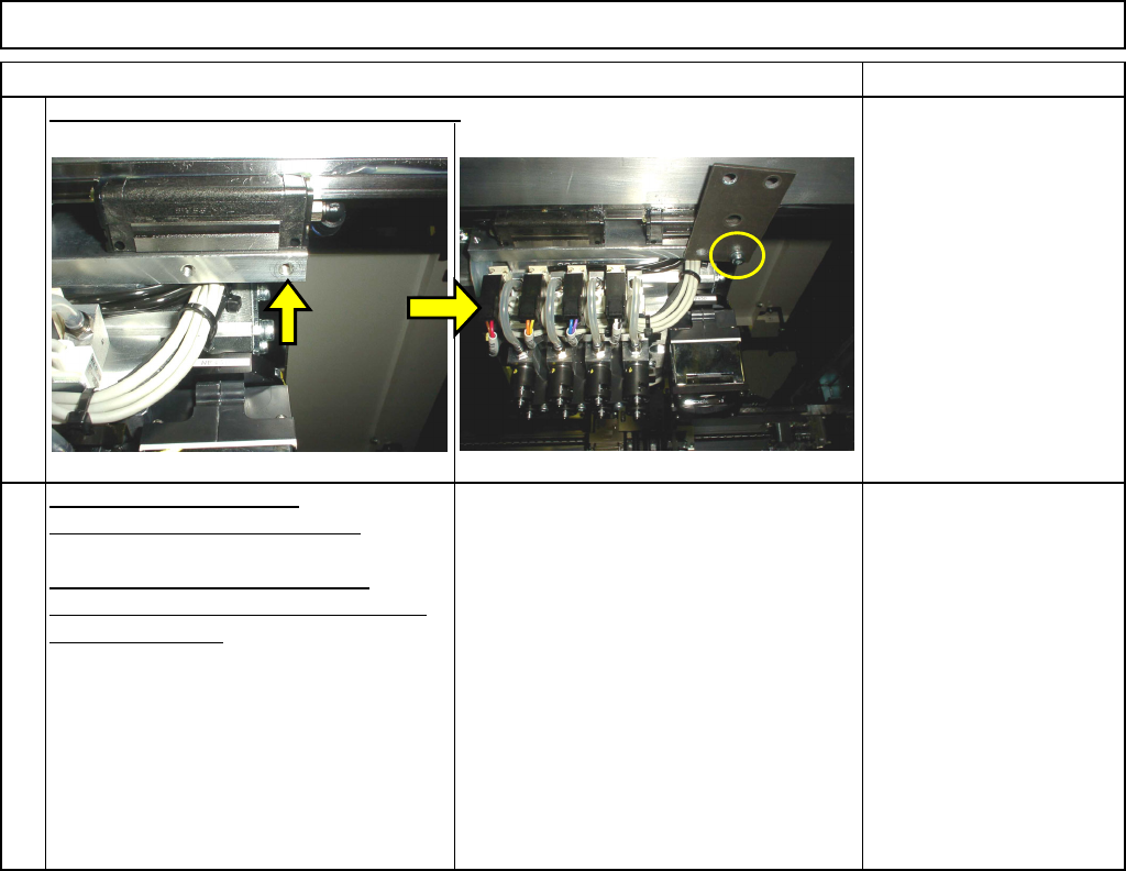
Remove the support pins.
Carry out the following teaching.
Determining the Mounting Height
and Positioning the Board
Mounting Position
Confirm the height. Remove the iron plate.
EJM8A-E-SMA040106-A01-00
Page 4-1-6-5
Maintenance Adjustment Main Body Beam
・Tools
Phillips screwdriver #2
Allen key 2.5 mm
Tape (opaque)
・Jig
FM-1055
Tape Float Sensor
Adjusting jig
4-1-7 Tape Float Sensor Adjustment
This section describes the procedures for adjusting the tape float sensor.
Caution
Dange
r
Warning
Assembly
Adjustment
10min.
Teaching
min.
Total Time Weight of
Part
Removal
Disassembly
10min.
20min.
kgs
EJM8A-E-SMA040107-A01-00
Page 4-1-7-1
Maintenance Adjustment Main Body Beam
Remarks
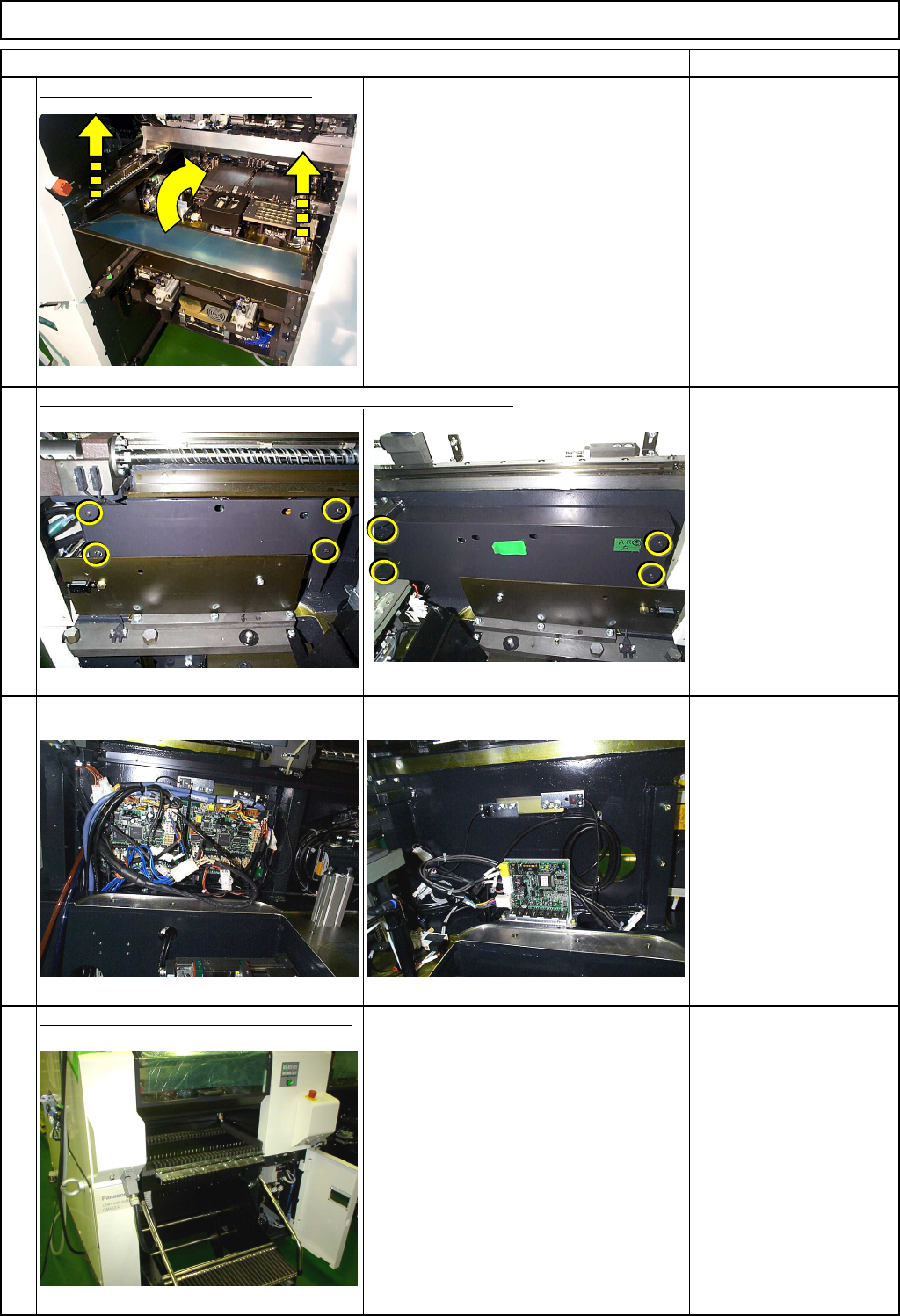
Remove the movable feeder cover.
Phillips screwdriver #2
Screw M4 2 pcs.
Remove the left and the right covers from the sensor section.
Phillips screwdriver #2
Screw M4 8 pcs.
Check the function of the sensors.
AF48/1143_0061bit7
AF52/1143_0062bit3
AR48/1143_00C1bit7
AR52/1143_00C2bit3
BF48/1143_0211bit7
BF52/1143_0212bit3
BR48/1143_0271bit7
BR52/1143_0272bit3
Install the tape feeder gang change cart.
Refer to "Feeder Gang Exchange Cart
Installation and Removal."
Since the feeder covers are left off, block
the light beam of "Tape Float Sensor 1"
with tape or equivalent.
Section 5-8-1
Tape
3
4
Item
2
1
EJM8A-E-SMA040107-A01-00
Page 4-1-7-2