CM602all_EJM8AESM_Service Manual.pdf - 第661页
Machinery Part Replacement Remark 12-Nozzle Head Unit Item Replace the Z-axis unit. Assemble the removed parts in reverse order of Steps 2 to 10. Put the head unit back on. See "12-Nozzle-Head-Unit Replacement."…
Machinery Part Replacement
Remark
12-Nozzle Head Unit
Item
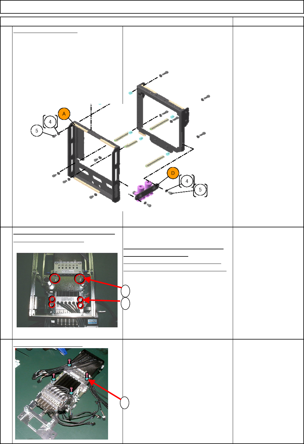
Remove the front frame.
Remove the seven M3 x 6L bolts (5).
Remove the front frame.
M3 x 6L 7 pcs.
Remove the fan bracket and the Z-
axis connectin
g
bracket.
1. Remove the two M3 x 20L bolts (1).
Remove the fan bracket.
2. Remove the four M3 x 6L bolts (2).
Remove the Z-axis connecting bracket.
M3 x 20L 2 pcs.
M3 x 6L 4 pcs.
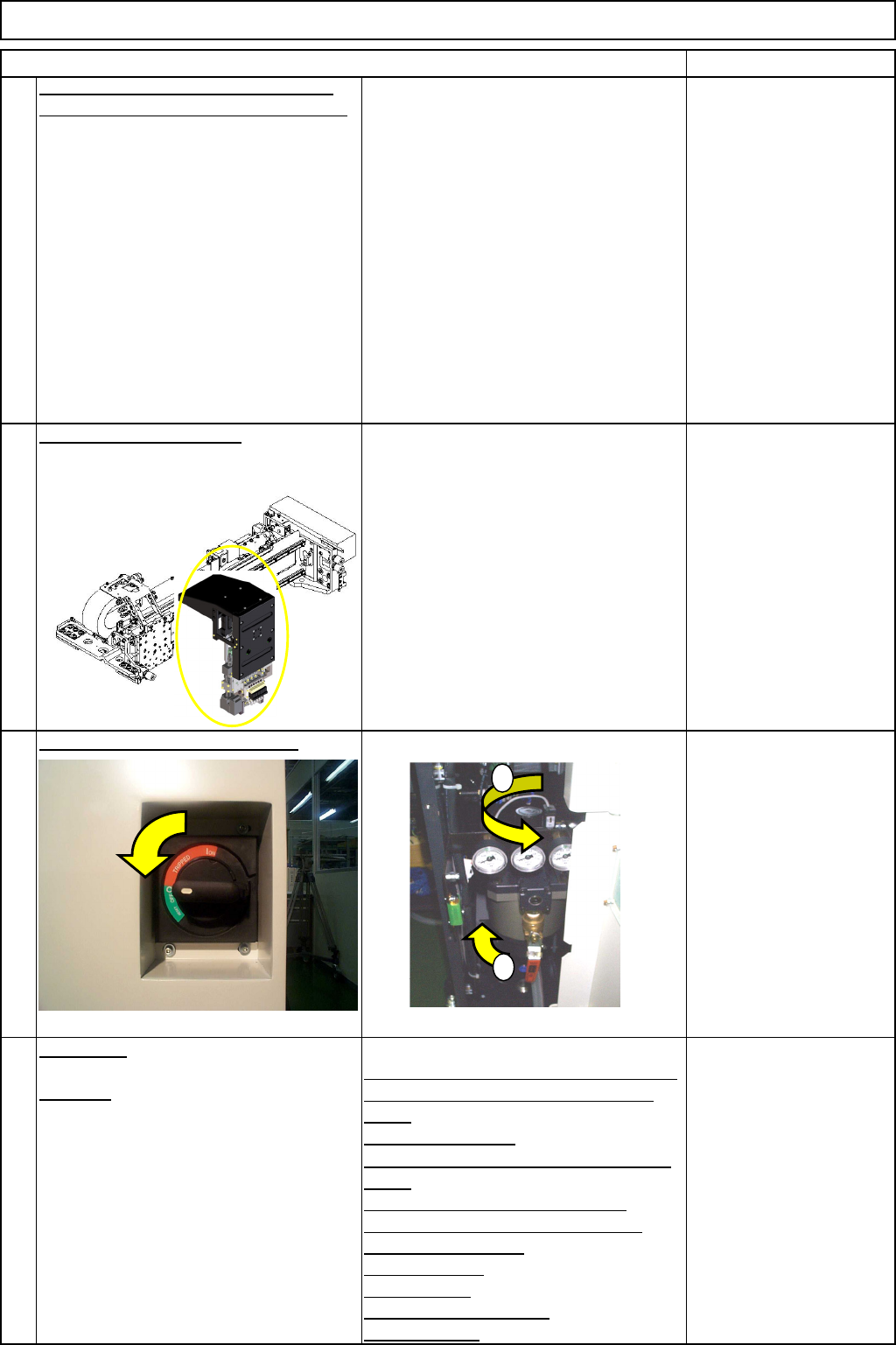
Remove the Z-axis unit.
1. Remove the four M5 x 25L bolts (1).
Remove the Z-axis unit.
* The Z-axis unit cannot be
disassembled. Be sure to replace a
whole unit.
M5x 25L 4 pcs.
9
10
11
1
2
1
EJM8A-E-SMA051009-A01-00
Page 5-10-9-5
Machinery Part Replacement
Remark
12-Nozzle Head Unit
Item
Replace the Z-axis unit. Assemble the
removed parts in reverse order of Steps
2 to 10.
Put the head unit back on.
See "12-Nozzle-Head-Unit
Replacement."
Section 5-10-1
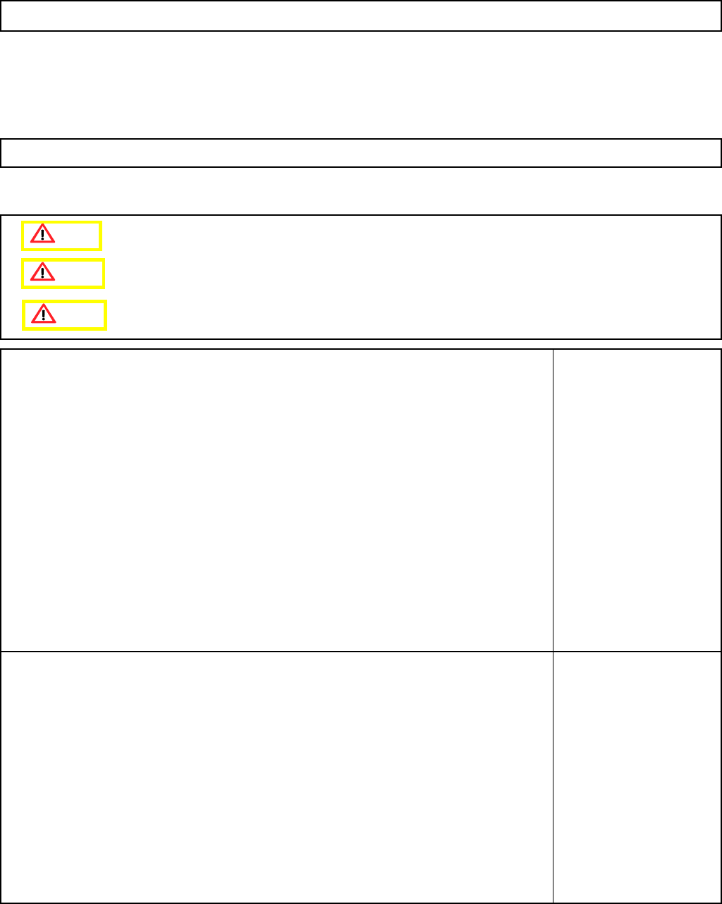
Turn on the power and air suppl
y
.
A
d
j
ustment
Teaching
Head Camera Adjustment (Focus and θ)
Board Recognition Camera XY Origin
Offset
Z-axis Origin Offset
Chip Recognition Camera, θ-axis Origin
Offset
Width Adjusting-axis Origin Offset
Mount Height and Board Positioning
XY Plane Calibration
Pickup Position
Light Intensity
Nozzle Change Position
Mount Position
Section 5-11-1
Section 5-11-2
Section 5-11-3
Section .5-11-4
Section 5-11-5
Section 5-11-6
Section 5-11-7
Section 5-11-8
Section 5-11-9
Section 5-11-10
Section 5-11-11
14
15
12
13
1
2
EJM8A-E-SMA051009-A01-00
Page 5-10-9-6
Machinery Part Replacement
This section describes the procedures for removing the clamp arm.
Tools
None
Jig
None
12-Nozzle Head Unit
5-10-10 Clamp Arm Replacement
Caution
Dange
r
Warning
EJM8A-E-SMA051010-A01-00
Page 5-10-10-1