CM602all_EJM8AESM_Service Manual.pdf - 第983页
Connect the signal cable to the CPU. Connect it to NF0FCX CN13. Fix the cover in place. Tray Phillips screwdriver #2 Allen key 3 mm M4 button head screw 4 pcs. M4 screw 6 pcs. 31 Replace the cover. Install the emergency …
Connect the power connector.
Be careful of the direction when
connecting it.
Allen key 2.5 mm
Screw M3 x 8 4 pcs.
Connect the Signal Cable 1 connector.
Be careful of the direction when
connecting it. Allen key 3 mm
Screw M4 x 8 4 pcs.
Connect the signal cable to Power Unit 1.
Connect the signal cable to Power Unit 2.
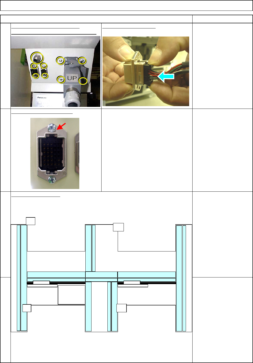
(2) Standard cables N2 to
N5 are not used.
Shuttle Tray
28
26
25
Tray
Item Remarks
27
(1) Secure the unused
short connector with a
cable tie.
(1) Secure the unused
short connector with a
cable tie.
Tie the cap strap to the upper left screw
as shown at left.
(2) Standard cables N2 to
N5 are not used.
UP
(1)
(2)
R2A+V R2A-V
TRY.EA
N2-N5
R2B+V
R2B-V
TRY.EB
N1-N9
(1)
(2)
UP
EJM8A-E-SMA070117-A01-00 Page 7-1-17-8
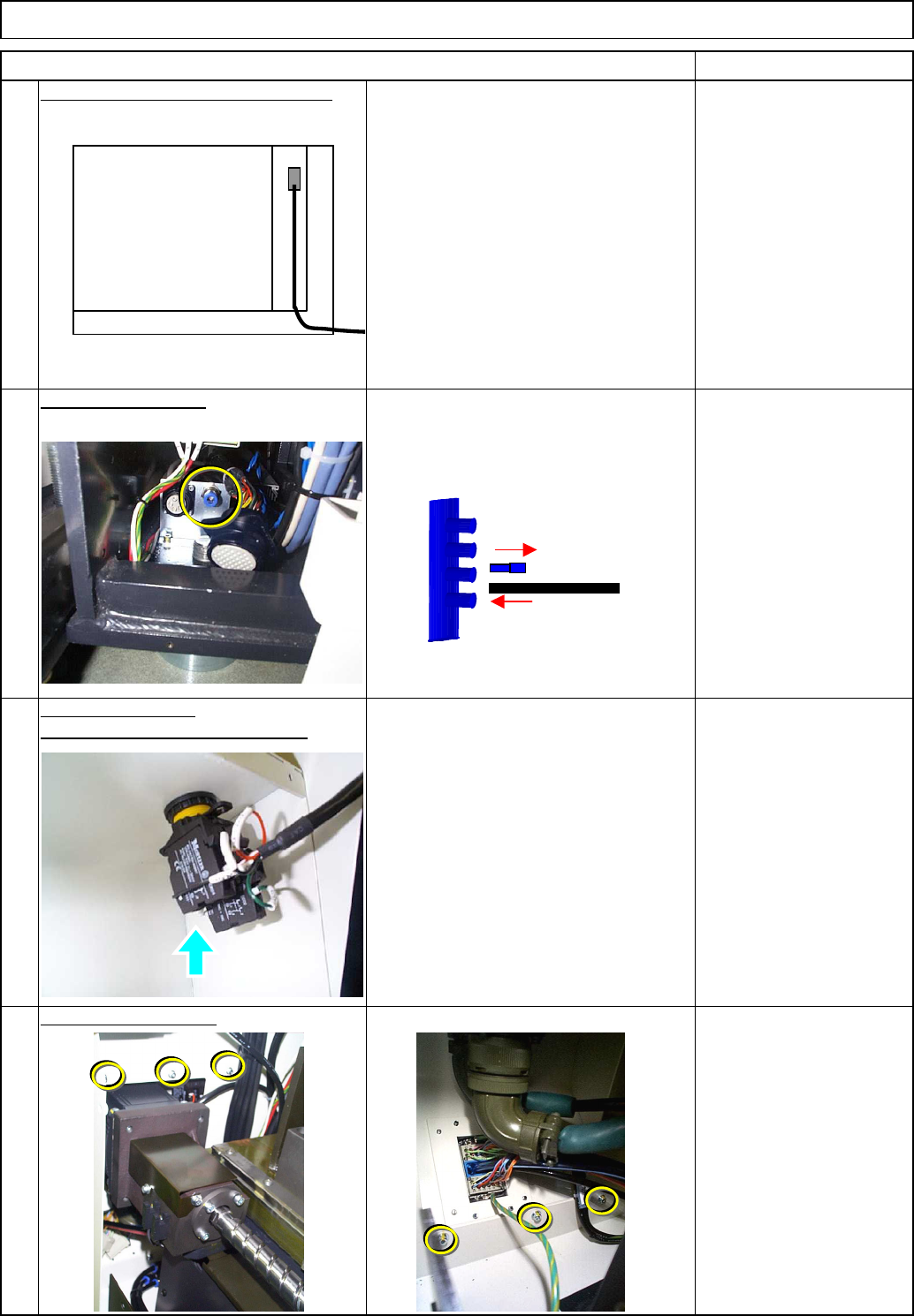
Connect the signal cable to the CPU.
Connect it to NF0FCX CN13.
Fix the cover in place.
Tray
Phillips screwdriver #2
Allen key 3 mm
M4 button head screw
4 pcs.
M4 screw 6 pcs.
31
Replace the cover.
Install the emergency stop button.
32
Item Remarks
Shuttle Tray
29
30
Connect the air tube.
CPU BOX
EJM8A-E-SMA070117-A01-00 Page 7-1-17-9
Connect the Si
g
nal Cable 2.
Philli
p
s screwdriver #1
Button head screw M3
2 pcs.
Put the Y-motor cover back on.
Insert it as shown below:
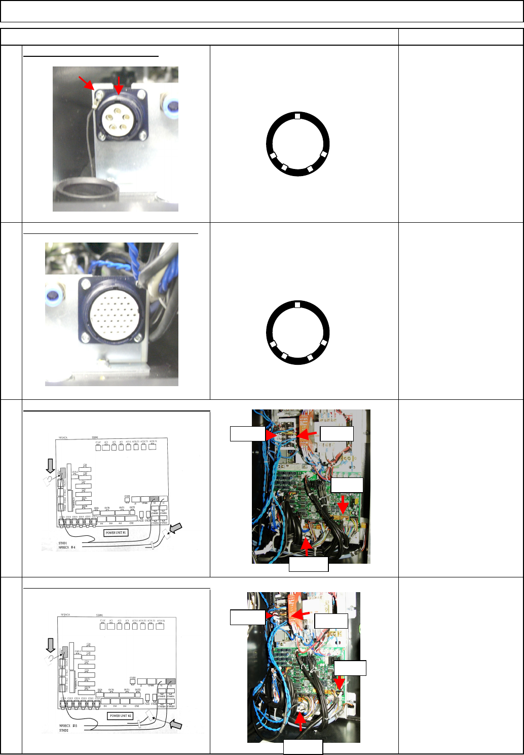
Secure the connectors with the screws.
Remove the screws from the non-used
connector cover, and hold the connector
with them.
Be careful of the direction when
connecting it.
The side with the maker name on should
be positioned top as shown at left.
34
36
35
Close the duct covers.
Remarks
33
Tray
Item
Shuttle Tray
A
POWER
UNIT#1
POWER
UNIT#2
CPU BOX
A
BF
BR
UP
EJM8A-E-SMA070117-A01-00 Page 7-1-17-10