CM602all_EJM8AESM_Service Manual.pdf - 第1025页
Min. Direct Tray • This section describes the procedures for adjusting the extension-axis stroke. Total Part Weight 80 FM-0544: Centering jig FM-1934: Lift-axis height check jig Min. 7-2-6 Lift-axis Motor Replacement Phi…

Another parameter
2
Name
PF18 For manufacturer setting
PF19 For manufacturer setting
PF20 For manufacturer setting
Another parameter
3
Name
For manufacturer setting
For manufacturer setting
For manufacturer setting
For manufacturer setting
No.
PO03
PO04
PO05
PO06
PO07
Tray
For manufacturer setting
TL-axis TP-axis
PO01
PO02
PO08
Option card mount detection
For manufacturer setting
0
0
0
0
0
0
0
0
0
0
0
0
0
0
0
0
00
0
0
0
0
TL-axis TP-axis
Direct Tray
Lift-axis (TL) and Extension-axis (TP) Parameter List
No.
For manufacturer setting
EJM8A-E-SMA070205-A01-00
Page 7-2-5-11
Min.
Direct Tray
• This section describes the procedures for adjusting the extension-axis stroke.
Total Part Weight
80
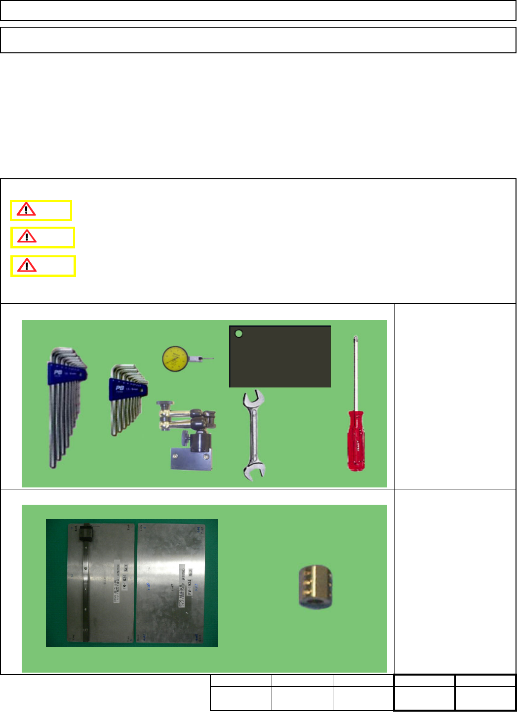
FM-0544: Centering jig
FM-1934: Lift-axis height
check jig
Min.
7-2-6 Lift-axis Motor Replacement
Phillips screwdriver #2
Allen key 3 mm
Allen key 5 mm
Wrench 14 and 19 mm
Dial gauge
Magnetic stand
Stand-mounting iron plate
Block gauge 10 mm
Teaching
Assembly/Adjustment
kgs.
Tool
Jig
Removal/Disassembly
Min. Min.
5030
Tray
Caution
Danger
Warning
EJM8A-E-SMA070206-A01-00
Page 7-2-6-1
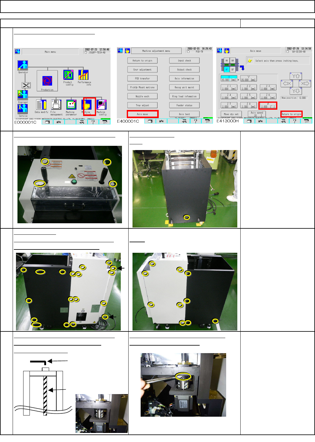
the bolt shown with the arrow below.
coupling to the front.
Item
Return the lift-axis to the origin.
1
Direct Tray
Phillips screwdriver #2
M4 screw 11 pcs.
Allen key 2.5 mm
M3 4 pcs.
Remark
Rear
2
Turning the ball screw, move the
Insert an Allen key into the ball screw.
hold the nut with a wrench.
Holding the Allen key with one hand,
Remove the cover. Turn off the power. Remove the bolt.
Phillips screwdriver #2
M4 screw 4 to 6 pcs.
Open the cover.
Left. Stay at the front side when removing
Right
Tray
3
4
Ball screw
Wrench 5 mm
EJM8A-E-SMA070206-A01-00
Page 7-2-6-2