CM602all_EJM8AESM_Service Manual.pdf - 第1030页
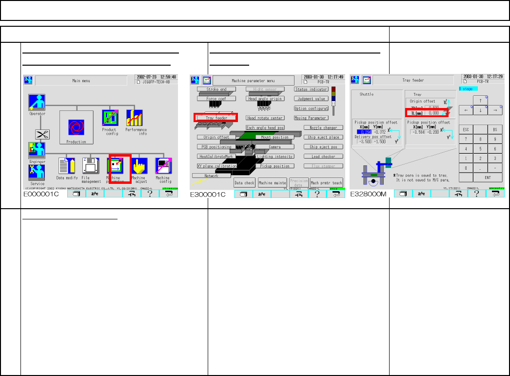
Remark Direct Tray Put the cover back on. 18 17 Item Input the measurement value into TL manually. Offset range: within +/- 1 This offset is stored in the tray, not in the machine. Tray EJM8A-E-SMA070206-A01-00 Page 7-2-…
Jig: FM-1934
Lift-axis height check jig
Item Remark
13
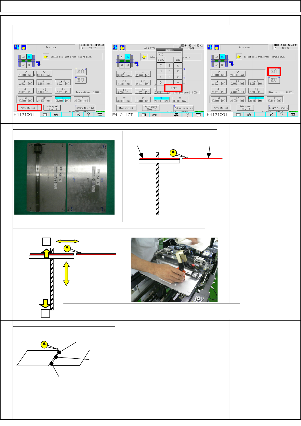
Raise the lift axis 422 mm.
Check the height of the lift table (extension section) and supply-section table.
Put a magnetic stand and a dial gauge on the lift-table side (extension section).
Specifications: within +/-1.0
mm
Magnetic stand
Dial gauge
16
Check the three measurement positions.
14
Direct Tray
Put the palette jig on the lift table (extension section) and the supply-section table.
Tray
15
422
Inside the range: Input an offset and move on to fine-tuning. (Step 16)
Outside the range: Return to Step 11(return-to-origin process)
+
-
Specifications:
within+/-1.0
Lift table
Supply-section table
A1 (right and left): within +/- 0.2 mm
A0 (center): within +/- 0.2 mm
A1 (right and left): within +/- 0.2 mm
Lift-axis ball screw
FM-1934
FM-1934
EJM8A-E-SMA070206-A01-00
Page 7-2-6-5
Remark
Direct Tray
Put the cover back on.
18
17
Item
Input the measurement value into TL
manually. Offset range: within +/- 1
This offset is stored in the tray, not in the
machine.
Tray
EJM8A-E-SMA070206-A01-00
Page 7-2-6-6
7-2-7
Part Weight
Min. Min.
Tray
Extension-axis Stroke Adjustment
• This section describes the procedures for adjusting the extension-axis stroke.
Total
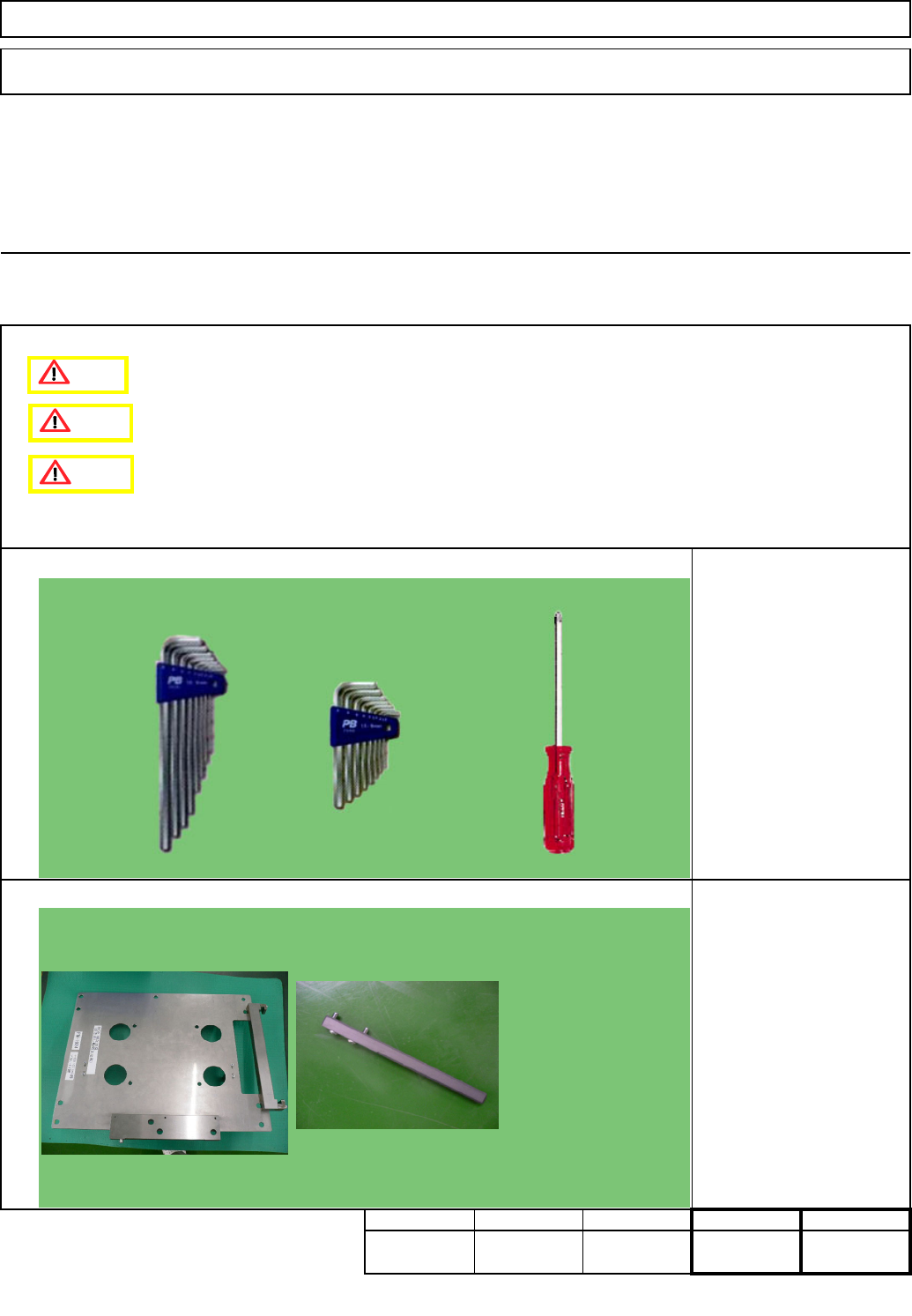
Phillips screwdriver #2
Allen key 2.5 mm
Allen key 4 mm
Teaching
Removal/Disassembly
Direct Tray
Min.
kgs.
0
Min.
Tool
Jig
Assembly/Adjustment
Jig FM-1924
Pulley-holding jig
Caution
Danger
Warning
EJM8A-E-SMA070207-A01-00
Page 7-2-7-1