CM602all_EJM8AESM_Service Manual.pdf - 第650页
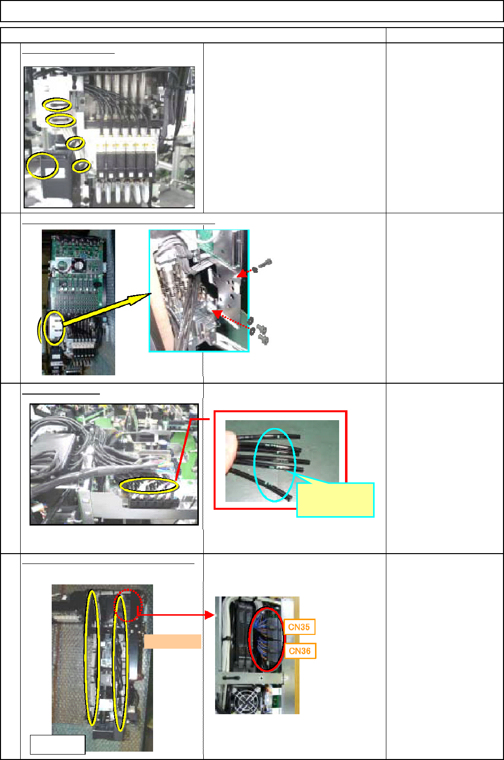
Machinery Part Replacement Remark 12-Nozzle Head Unit Item Remove the tube-holding bracket. Allen key M3 x 6L 2 pcs. Cut off the cable tie for the θ moto r cable. Remove the tube. Nipper Remove the component thickness se…
Machinery Part Replacement
Remark
12-Nozzle Head Unit
Item
Cut off the cable ties.
When removing the tube, put a mark on
the tubes so that they can put back in the
same place.
Nipper
Magic marker
Remove the cable and tube holding bracket.
Allen key
M3 x 6L 3 pcs.
Remove the tube.
Magic marker
Remove the vacuum-sensor connector.
Cut off the cable tie.
Nipper
5
6
8
7
Put a mark
here.
<Left side>
Front
EJM8A-E-SMA051008-A01-00
Page 5-10-8-3
Machinery Part Replacement
Remark
12-Nozzle Head Unit
Item
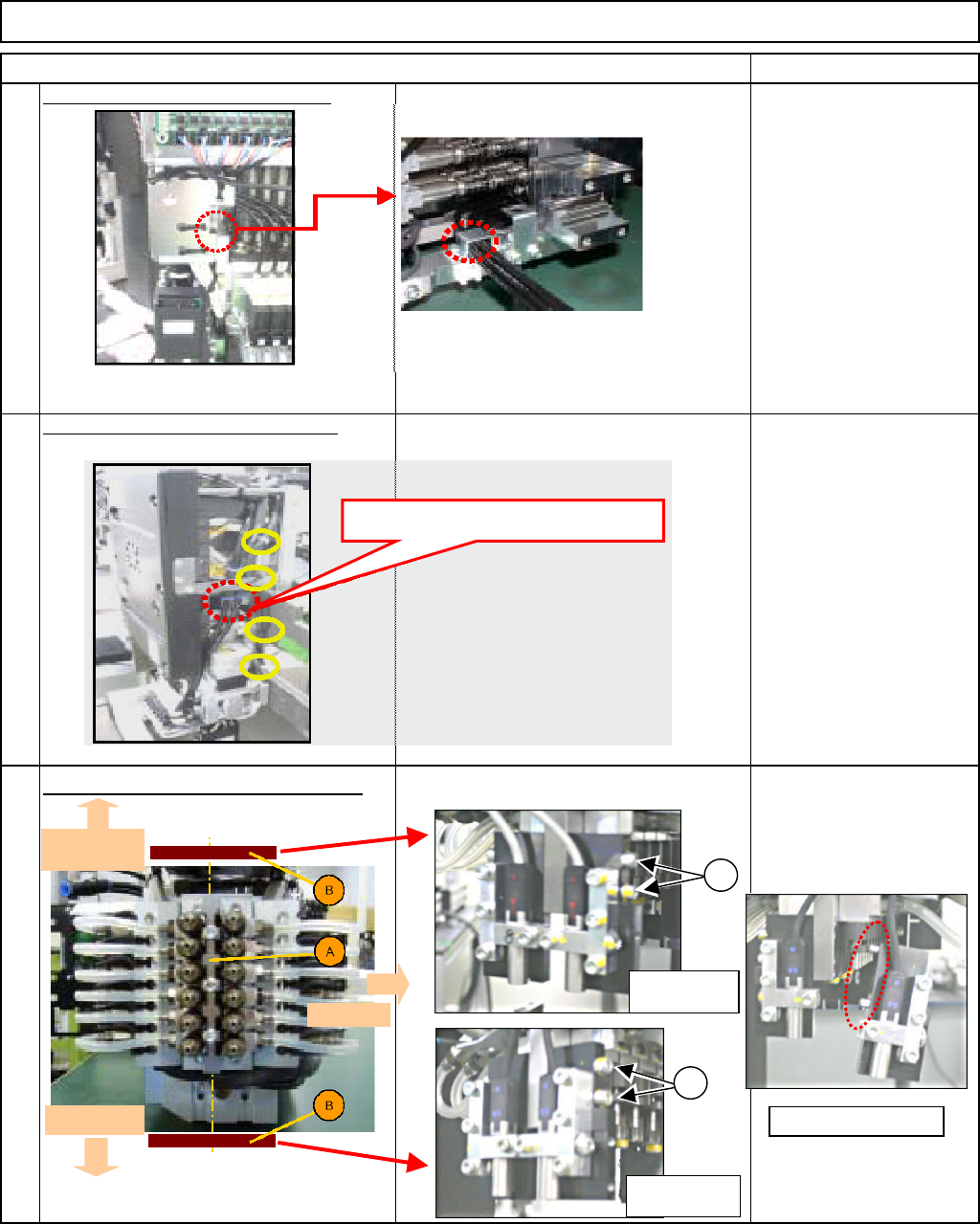
Remove the tube-holding bracket.
Allen key
M3 x 6L 2 pcs.
Cut off the cable tie for the
θ moto
r
cable. Remove the tube.
Nipper
Remove the component thickness sensor.
Loosen the cbolts. Remove the component
thickness sensor alon
g
with the
p
late.
Allen key
11
9
10
Remove the tube here.
Head-camera
side
θ
-motor side
Front side
1
1
Light-sensing
device
Light-emitting
device
Remove the pin.
EJM8A-E-SMA051008-A01-00
Page 5-10-8-4
Machinery Part Replacement
Remark
12-Nozzle Head Unit
Item
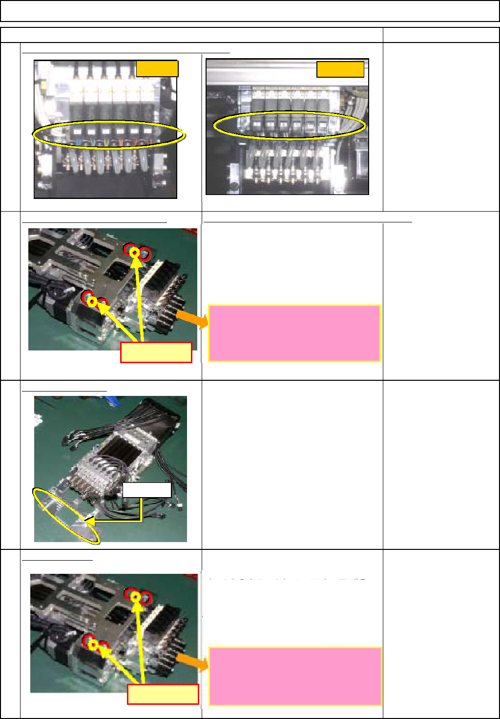
Remove the vacuum-switching-valve connector.
Remove the θ-unit holdin
g
screw.
Insert the plate. Lower the shaft 20 mm or more.
Allen key
M5 x 12L 4 pcs.
Se
p
arate the θ unit.
Install the θ unit.
Installation procedures are described below.
Allen key
M5 x 12L 4 pcs.
12
13
15
14
FWD側
REAR側
FWD
REAR
Pin positions
The ball-spline shafts should be
extended so that the ends of the
shafts do not touch any other parts
when mounting the unit on the θ-axis.
ピン位置
Insert the plate. Lower the shaft 20 mm
or more.
Aligning the θ unit with the dowel pins,
fix the unit in place.
The ball-spline shafts should be
extended so that the ends of the
shafts do not touch any other parts
when mounting the unit on the θ-axis.
Dowel pin
Pin positions
EJM8A-E-SMA051008-A01-00
Page 5-10-8-5