CM602all_EJM8AESM_Service Manual.pdf - 第777页
Remark Item Component-Thickness-Measuring Unit Option Part and Accessory Replacement Open the connector lock. Remove the sensor cables from the a m p lifi e r co nn ecto r l oc k s . Pre p are the am p lifier ( substitut…
Remark
Item
Component-Thickness-Measuring Unit
Option Part and Accessory Replacement
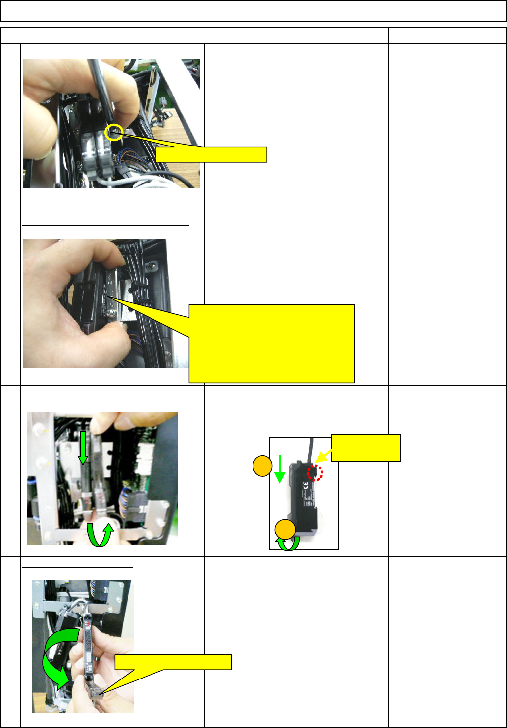
Remove the am
p
lifier-hodi
g
bolt. -
(
1
)
8
Phillips screwdriver #2
Screw M4
Remove the am
p
lifier-hodi
g
bolt. -
(
2
)
9
Remove the am
p
lifier.
Move the amplifier in the (1) and (2)
directions below, and remove the
amplifier.
O
p
en the am
p
lifier cover.
11
10
Open the amplifier cover.
Loosen the holding bolt.
Move the bracket in the ↑ direction.
Pull the bolt-less end of the bracket
towards you to unlcok that end.
Move the bracket in the ↓ direction
to unlock the bolt end of the bracket.
Remove the bracket.
1
2
This hook can
move.
EJM8A-E-SMA060401-A01-01
Page 6-4-1-4
Remark
Item
Component-Thickness-Measuring Unit
Option Part and Accessory Replacement
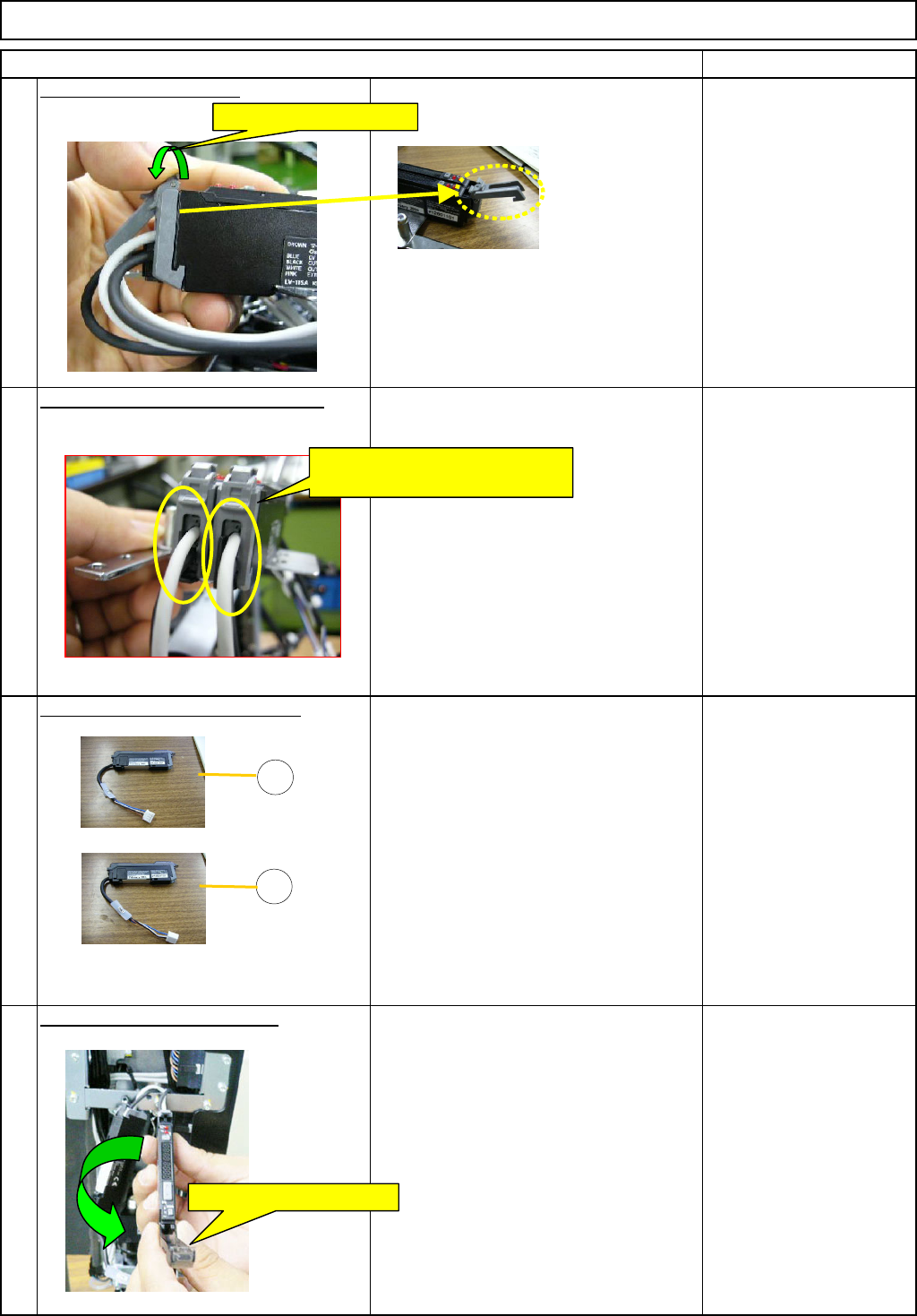
Open the connector lock.
Remove the sensor cables from the
a
m
p
lifi
e
r
co
nn
ecto
r l
oc
k
s
.
Pre
p
are the am
p
lifier
(
substitute
)
(1) AMP LV11SA(CN39)
(2) AMP LV11SA(CN40)
O
p
en the new am
p
lifier cover.
12
13
14
15
Open the connector lock
Remove the sensor cables from
the amplifier connector locks.
1
2
Open the amplifier cover.
EJM8A-E-SMA060401-A01-01
Page 6-4-1-5
Remark
Item
Component-Thickness-Measuring Unit
Option Part and Accessory Replacement
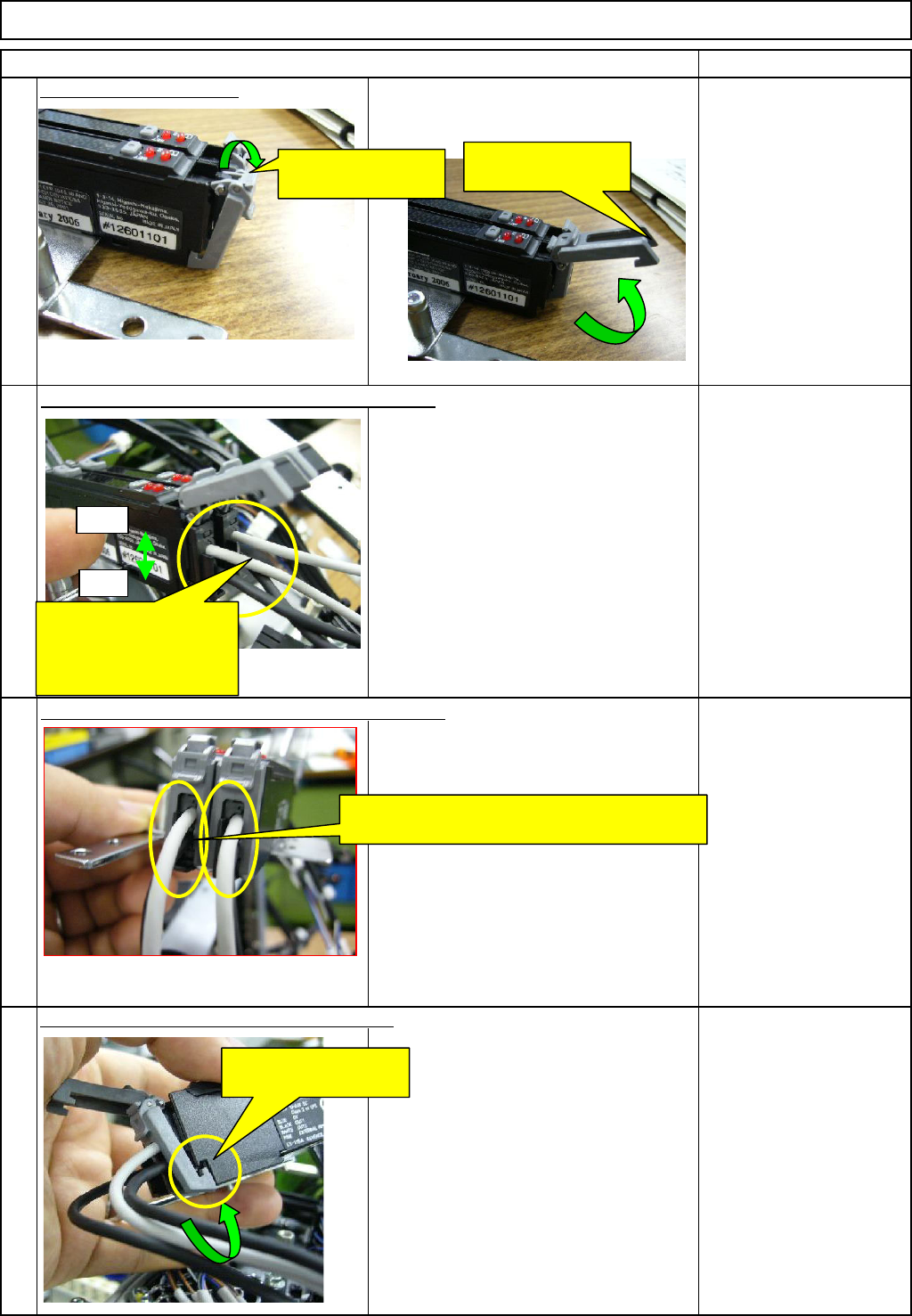
O
p
en the connector lock.
(1) Insert the light-emitting cable (gray) for the
nozzle front line (1 to 6) into the front side of
the amplifier connector 40.
Next, insert the light-sensing cable (black) for
the nozzle front line (1 to 6) into the rear side
of the amplifier connector 40.
(2) Insert the light-emitting cable (gray) for the
nozzle rear line (7 to 12) into the front side of
the amplifier connector 39.
Next, insert the light-sensing cable (black) for
the nozzle rear line (7 to 12) into the rear side
of the amplifier connector 39.
16
19
17
18
Insert the sensor cable into the am
p
lifier. -
(
1
)
Insert the sensor cables into the am
p
lifier. -
(
2
)
Put the connector-lock hook on the amplifier.
Open the connector
lock.
Open the connector
lock.
Front
Rear
Put the sensor cables between the connector
locks of the amplifier.
Insert the sensor cables
for the front (1 to 6) and
for the rear (7 to 12) into
the amplifier.
Put the connector-lock
hook on the amplifier.
EJM8A-E-SMA060401-A01-01
Page 6-4-1-6