CM602all_EJM8AESM_Service Manual.pdf - 第357页
I Since this adjustment requires releasing the safety cover switch, only those who are authorized to release it based on the Document "Key Switch/Key Disk Receipt Confirmation and Safety Precautions" are permit…
Machine Part Replacement
27
Put the feeder cover back on.
Wrench 3 mm
Screw M4 (Special) 3 pcs.
26
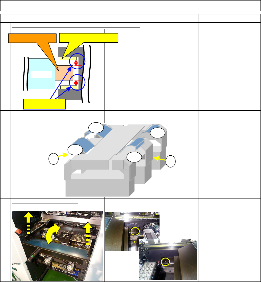
Put the side covers back on.
* Use a non-magnetic
material when checking
the gap.
Gap: 0.3 - 0.8 mm
Check the gap between the primary and secondary parts.
Item
Main Body
25
Remarks
Y-axis primary part
Y-axis secondary part
0.3 - 0.8 mm
X-axis
AF
BR
AR
BF
1
2
EJM8A-E-SMA050107-A01-00 Page 5-1-7-8
I Since this adjustment requires releasing the safety cover switch, only those who are
authorized to release it based on the Document "Key Switch/Key Disk Receipt
Confirmation and Safety Precautions" are permitted to perform this adjustment.
Removal/Disassembly
Teaching
Assembly/Adjustment
• This section describes the procedures for replacing the Y-axis primary-part.
Total Time Part Weight
Y-axis primary-part sliding
stand
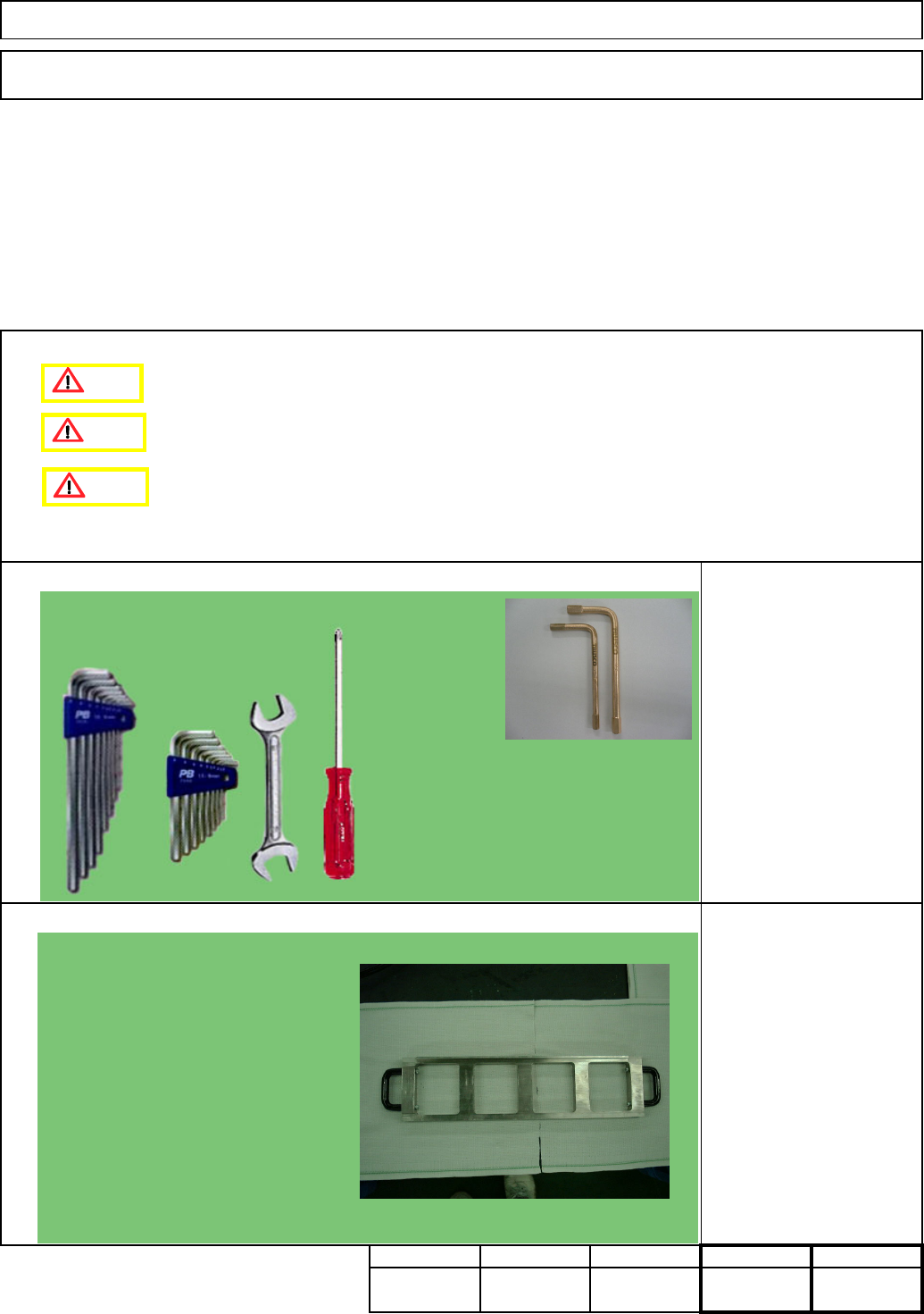
Tools
Jig
Phillips screwdriver #2
Allen keys 3 - 5mm
Wrench 14 and 19 mm
Non-magnetic Allen key
180
Min.
kg
90Min.90 Min.Min.
Main Body
5-1-8 Y-axis Primary-Part Replacement
Machinery Part Replacement
Caution
Danger
Warning
Non-magnetic Allen key (Straight)
Should be short-processed.)
Picture: Manufacturer: TRUSCO
NAKAYAMA
Flame-proof tool series
Model: BHX-4, BHX-5 (Size M4 and M5)
EJM8A-E-SMA050108-A01-00
Page 5-1-8-1
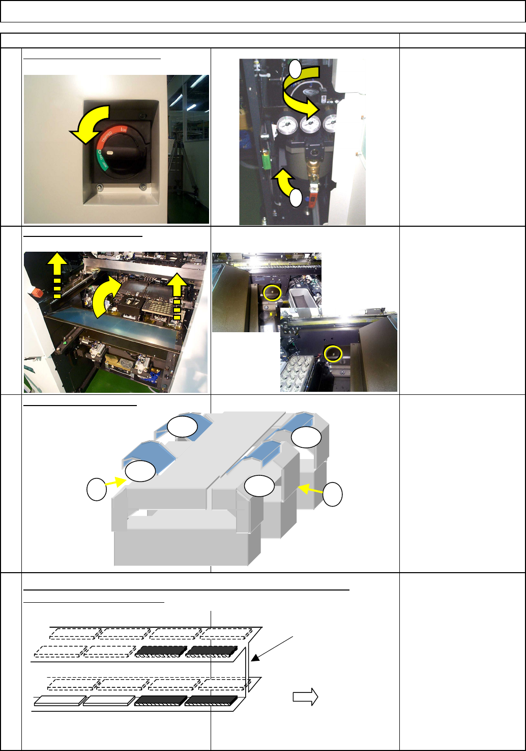
Remove the secondary parts from the desired stage, referring to "Y-axis
Secondary-Part Replacement."
3
4
Remarks
Main BodyMachine Part Replacement
Wrench 3 mm
Screw M4 (Special) x 2
1
Item
Turn off the power and the air.
Remove the side covers.
Remove the feeder cover.
2
1
2
AF
BR
AR
BF
1
2
Stage A
Stage B
Operator's side
Ex. Remove the four secondary-parts from the AF as shown above.
Center frame
EJM8A-E-SMA050108-A01-00
Page 5-1-8-2