CM602all_EJM8AESM_Service Manual.pdf - 第985页
Put the machine side covers back on. Philli p s screwdriver #2 stages on the rear side. Put the side covers back on all the Remarks Allen key 4 mm M5 x 12 mm 4 pcs x 4 Thick washer 4 pcs x 4 Put all lower chutes back on.…
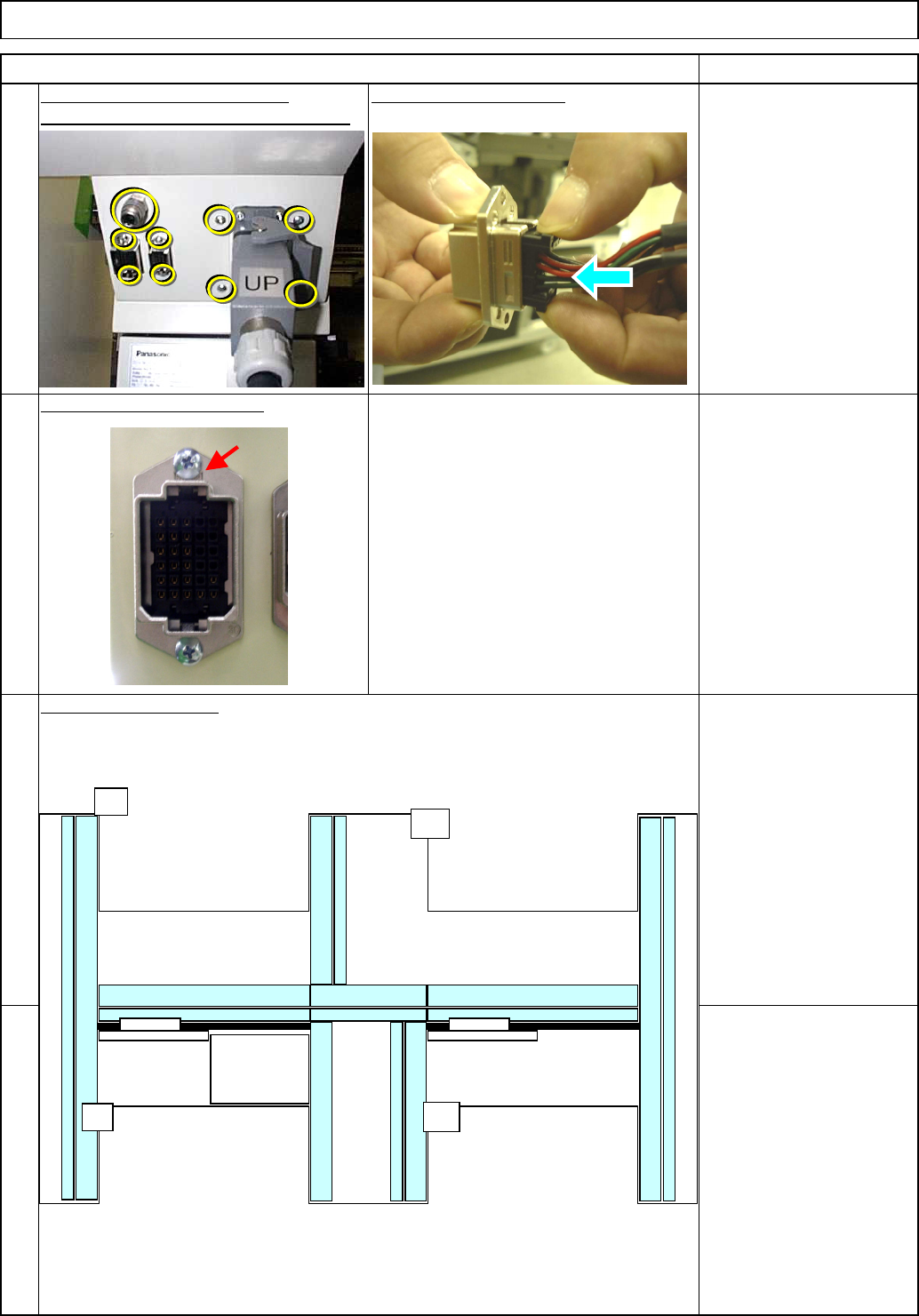
Connect the Si
g
nal Cable 2.
Philli
p
s screwdriver #1
Button head screw M3
2 pcs.
Put the Y-motor cover back on.
Insert it as shown below:
Secure the connectors with the screws.
Remove the screws from the non-used
connector cover, and hold the connector
with them.
Be careful of the direction when
connecting it.
The side with the maker name on should
be positioned top as shown at left.
34
36
35
Close the duct covers.
Remarks
33
Tray
Item
Shuttle Tray
A
POWER
UNIT#1
POWER
UNIT#2
CPU BOX
A
BF
BR
UP
EJM8A-E-SMA070117-A01-00 Page 7-1-17-10
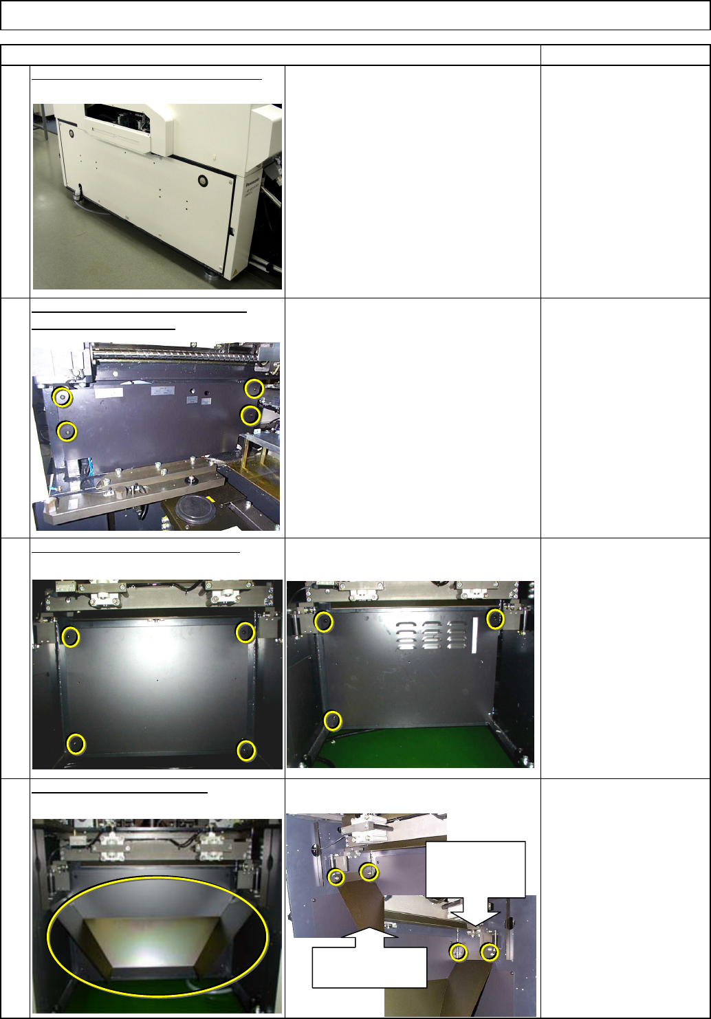
Put the machine side covers back on.
Philli
p
s screwdriver #2
stages on the rear side.
Put the side covers back on all the
Remarks
Allen key 4 mm
M5 x 12 mm 4 pcs x 4
Thick washer 4 pcs x 4
Put all lower chutes back on.
Phillips screwdriver #2
Button head screw 6mm
4 pcs.
(3 pcs on AF)
38
40
39
37
Tray Shuttle Tray
Item
Put the lower box covers back on.
Left chute
installing section
Right chute
installing
section
EJM8A-E-SMA070117-A01-00 Page 7-1-17-11
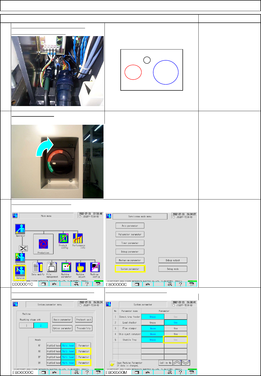
Fix the bracket in place.
Turn on the power.
Shuttle Tray
41
Fit the connectors and the joints.
Item
Connect a short connector
to the signal cable for the
unused stage. (Otherwise,
the monitor will be
locked.)
Select the stage on which the shuttle
Set "Shuttle Tray" to "Use."
tray will be installed. (AR or BR)
Change the specifications.
42
Tray
44
43
Remarks
Tray power
Tray signal
cable
Tray air joint
EJM8A-E-SMA070117-A01-00 Page 7-1-17-12