CM602all_EJM8AESM_Service Manual.pdf - 第979页
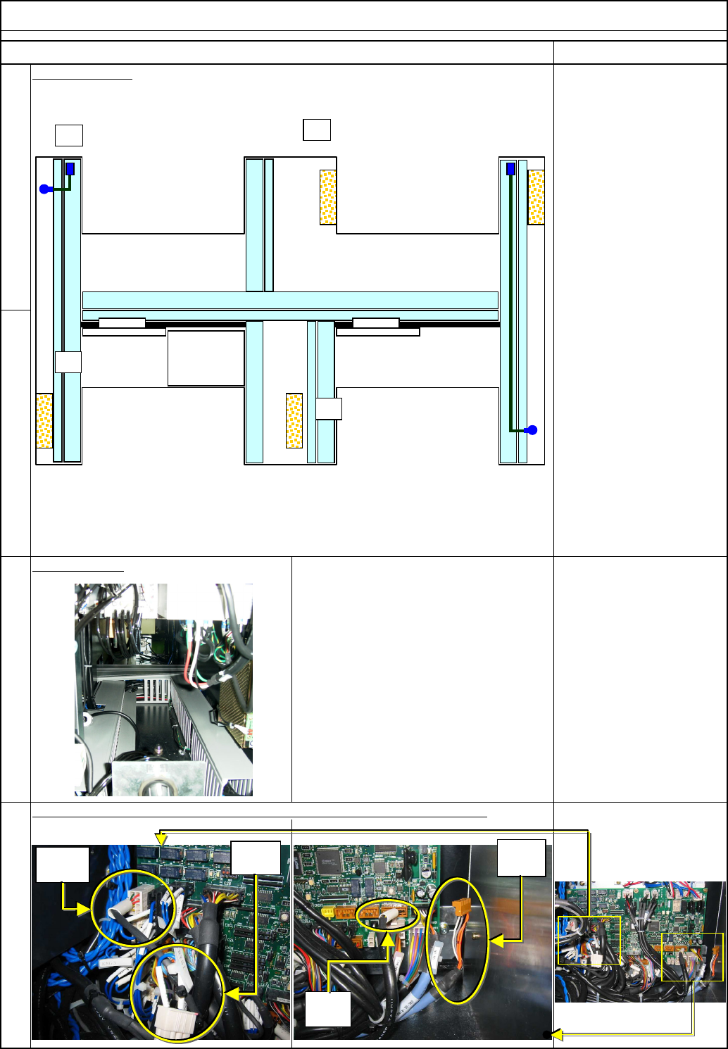
Nipper Replace the current cable with the standard cable.(2 pcs. for each stage) Tray Shuttle Tray 14 Item 13 Air Tube Layout Remarks 15 16 Duct example: TRY.S A Non- used Non- used N2-N5 N1-N9 POWER UNIT#1 POWER UNIT#2 …
(1) Standard Cable Connectors N2 to N5 are not used.
(2) The standard connector TRYS1 should be secured near RY.SA with a cable tie.
(3) Standard Cable Connectors N1 to N9 are not used.
(4) The standard connector TRYS1 should be secured near TRY.SB with a cable tie.
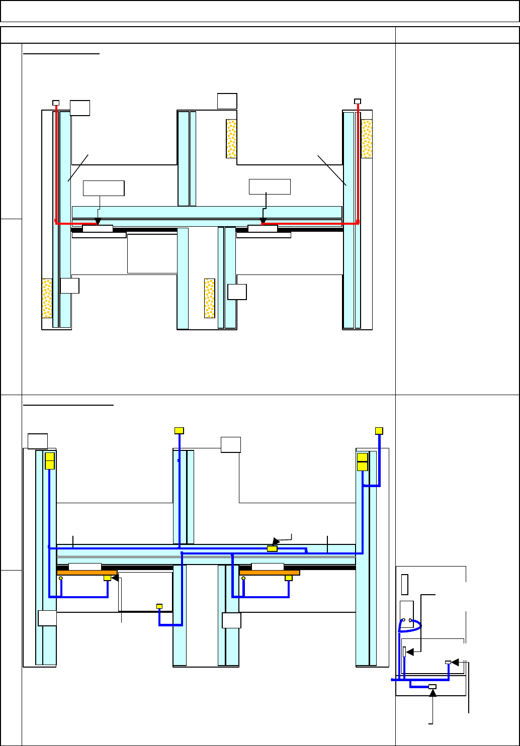
AC Cable Layout
11
10
12
9
91030:
A stage tray signal cable
91040:
B stage tray signal cable
Signal Cable Layout
Item Remarks
Shuttle Tray
91010:
TYR.P1 to TYR.R1
91020:
TYR.P2 to TYR.R2
Tray
AF
TYR.P2
POWER
UNIT#1
POWER
UNIT#2
CPU BOX
AR
BF
BR
TYR.P1
TYR.R1
TYR.R2
9102091010
AF
POWER
UNIT#1
POWER
UNIT#2
CPU BOX
AR
BF
BR
RF2RF2 TRY.SB
N1-N9
TRY.SA
N2-N5
NF0FCX
CN13-NJ
STCV11 STCV21
STHD2
STHD-S
STHD1
STHD-S
ITRY-P/R
91030
91040
Connection of Power Unit
RF1
RF2
NF2ACX
TRY EP
Change to a
short connector.
Change to the
standard cable.
EJM8A-E-SMA070117-A01-00 Page 7-1-17-4
Nipper
Replace the current cable with the standard cable.(2 pcs. for each stage)
Tray Shuttle Tray
14
Item
13
Air Tube Layout
Remarks
15
16
Duct example:
TRY.S
A
Non-
used
Non-
used
N2-N5
N1-N9
POWER
UNIT#1
POWER
UNIT#2
CPU BOX
AR
BF
BR
AF
EJM8A-E-SMA070117-A01-00 Page 7-1-17-5
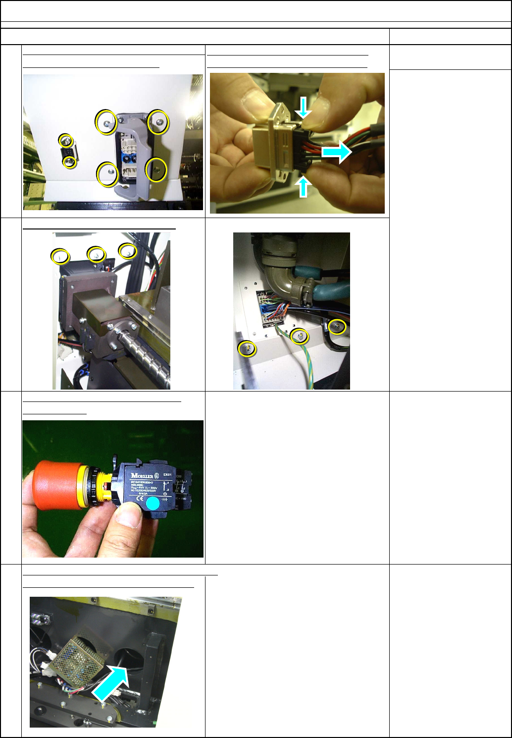
Remove the cover holding screws.
To use the shuttle tray, change the cover
When the NAVI system is installed, remove
the power unit from the BR right stage.
Allen key 2.5 mm
To secure space in which the STCV 1
cable is connected.
pull it out along the horizontal arrow.
Remarks
Remove the Y-motor cover from the rear side
.
Hold it along the vertical arrows and
Tray Shuttle Tray
Phillips screwdriver #2
Allen key 3 mm
M4 button head screw 4
pcs.
M4 screw 6 pcs.
Item
Remove the emergency stop button
20
17
and the cover.
Remove the connector screws.
19
18
EJM8A-E-SMA070117-A01-00 Page 7-1-17-6