CM602all_EJM8AESM_Service Manual.pdf - 第1056页
, 14 16 Position the bearing with the jig. How to set the jig (right picture) Jig: FM-1924 The dowel pin of the jig should be inside of the LM, and the hollow of the rear side of the jig should be on the LM. 15 Move the …
10
11
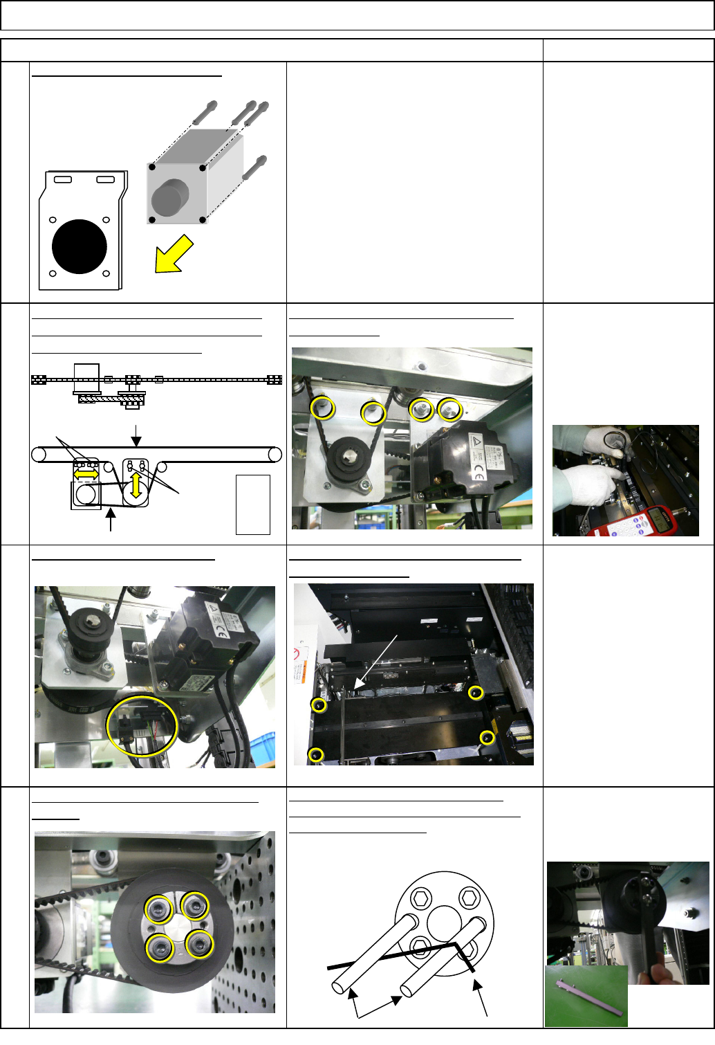
Put the belt in place. Tension it at the
motor section. Loosen B Tension the
belt in the order of A and B.
Loosen the power locks on the motor
section.
12
Allen key 4 mm
Screw M5 4 pcs.
When loosening, use an Allen key and
screws as shown below so that the power
locks will not be moved. After loosening,
lightly hitting the power locks unlocks the
lock. Jig available (right picture)
Allen key 2 mm
Phillips screwdriver #1
M3 6 pcs.
Truss 6 pcs.
Tension gauge
F1 48.5 +/- 3 Hz
F2 231 +/- 17 Hz
Item Remark
four Hexagon bolts.
Connect the motor connector. Put the palette table back on with the
Allen key 4 mm
Screw M5 4 pcs.
9
Put the motor bracket back on.
Tray Direct Tray
Check the tensions F1 and F2 with a
tension gauge.
F1=48.5Hz
A
B
F2=231Hz
Screw M5×40
Allen key
TP-axis
Supply
section
EJM8A-E-SMA070210-A01-00
Page 7-2-10-4
,
14
16
Position the bearing with the jig.
How to set the jig (right picture)
Jig: FM-1924
The dowel pin of the jig should be inside of the LM,
and the hollow of the rear side of the jig should be on
the LM.
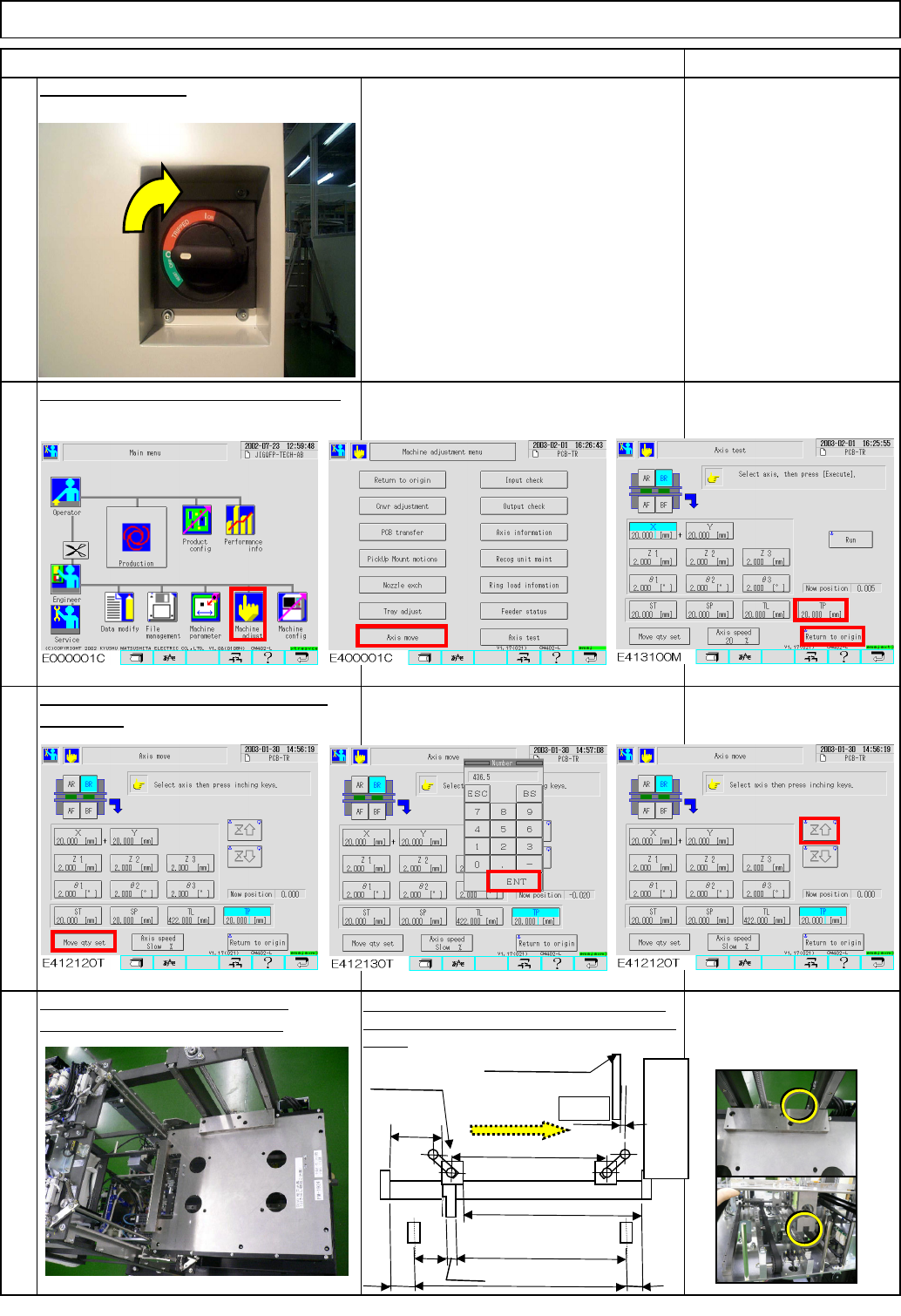
15
Move the extension axis towards you
382.5 mm.
Return the extension-axis to the origin.
Item Remark
13
Turn on the power.
Since the cover is open,
no one but the adjuster is
allowed to work on the
machine.
Tray Direct Tray
436.5
A=382.5
Origin
E
C
D
(
392.5
)
6
F
Magazine
(2)
(51)
Supply section
B=9
EJM8A-E-SMA070210-A01-00
Page 7-2-10-5
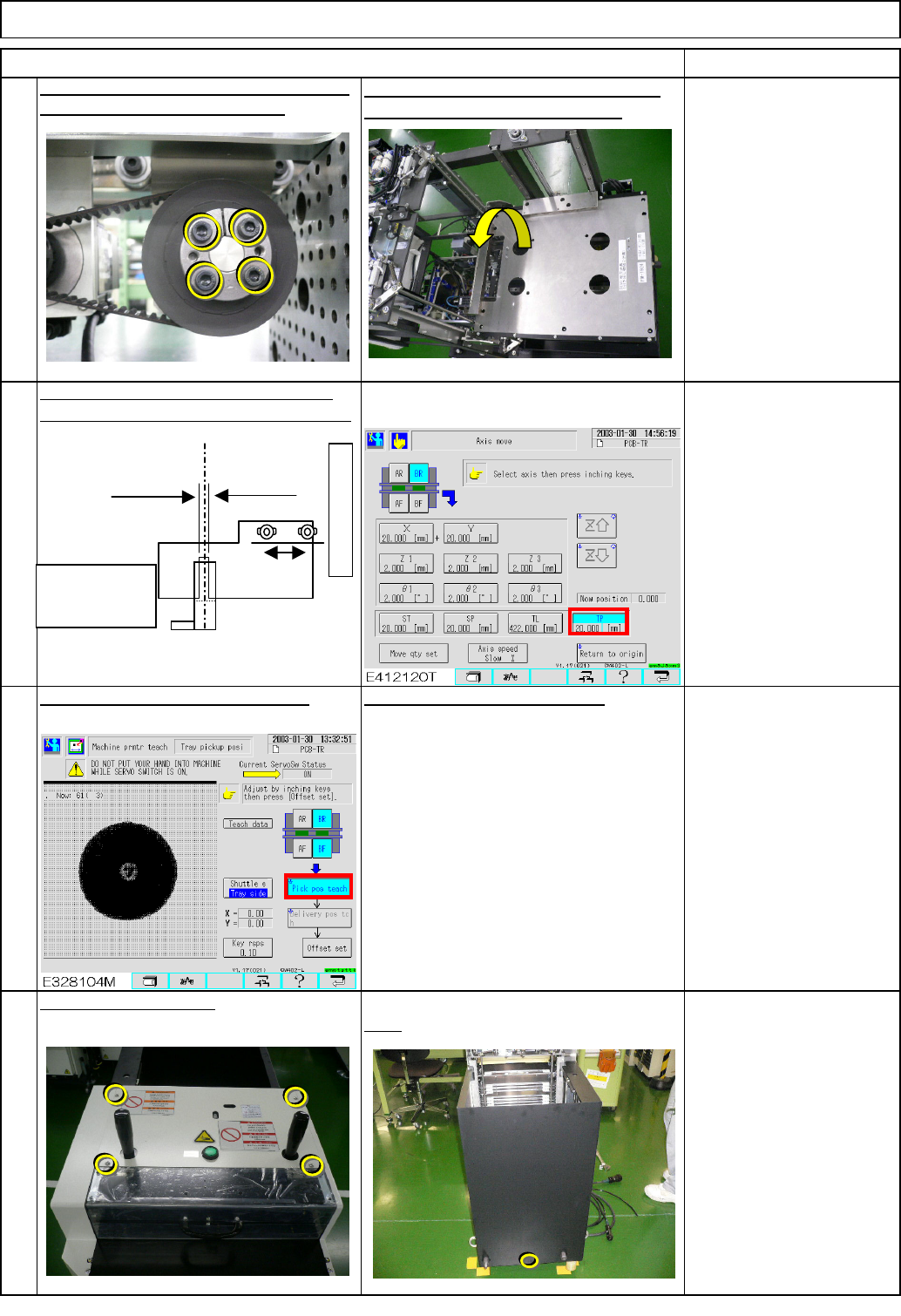
19
Carry out pickup position teaching.
Rear
Phillips screwdriver #2
Screw M4 4 to 6 pcs.
20
Put the cover back on.
See the followings:
Section 7-2-2 Direct Tray
Pickup Position Teaching
Section 7-2-3 Magazine
Shutter Stopper Position
Adjustment
18
Position the dog slit at the extension-axis
position. Move the axis with a 0.1-mm pitch.
Allen key 2.5 mm
M3 screw 2 pcs.
Position the magazine stopper.
17
Torque wrench 9.8 N•m
Allen key 4 mm
M5 screw 4 pcs.
Tighten the motor power locks with a torque
wrench. Tightening torque: 9.8N•m
After tightening, the bearing should be
turned manually. Remove the jig.
Tray Direct Tray
Item Remark
Magazine side
(0.5 mm)
Lift side
(1.0 mm)
Optical-axis sensor
Extension position PH sensor PH732
Dog
Supply section
Light through: ON
Light blocked: OFF
Light blocked at the mechanical stopper
in the - (supply) direction
EJM8A-E-SMA070210-A01-00
Page 7-2-10-6