CM602all_EJM8AESM_Service Manual.pdf - 第1067页
1. Tray Control (NF24CB) Board Setting z Ring channel setting • Ring channel auto judgment: Common to Stages A and B MODESW: 5 SWCH: 0 z Others (Jumpers and switches) The same setting as before JP1: OPEN JP2: OPEN JP3: S…
1. La
y
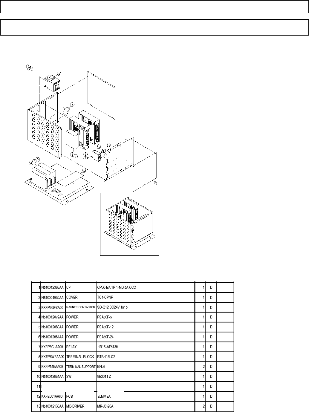
out of the Tra
y
-Box Part
s
(
1
)
AC200V circuit
p
rotector
(
2
)
Circuit
p
rotector terminal cover
(
3
)
Driver
p
ower ma
g
net rela
y
(
4 DC5V
p
ower source
(
5
)
DC12V
p
ower source
(
6
)
DC24V
p
ower source
(
7
)
Safet
y
rela
y
(
8
)
AC200V rela
y
terminal box
Driver control
p
ower and ma
g
net rela
y
(
9
)
Safet
y
rela
y
terminal block
(
10
)
Brake release switch
(
11
)
Tra
y
control board
(
NF24CB
)
(
12
)
Tra
y
(
Driver
)
rela
y
board
(
ELMMEA
)
(
13
)
Ri
g
ht: Lift-axis driver
Left: Extension-axis driver
Note: The same driver, but different
p
arameters
Part Numbers and Model
s
7-2-15 Layout of the Tray-Box Parts
Direct TrayTray
NF24C
N610044402AA
EJM8A-E-SMA070215-A01-00
Page 7-2-15-1
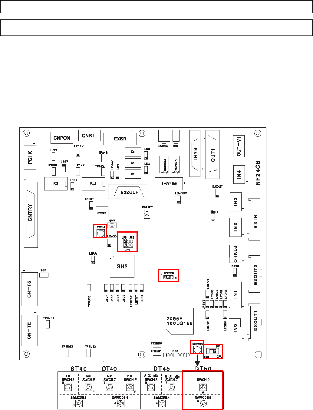
1. Tray Control (NF24CB) Board Setting
zRing channel setting
• Ring channel auto judgment: Common to Stages A and B
MODESW: 5
SWCH: 0
zOthers (Jumpers and switches) The same setting as before
JP1: OPEN JP2: OPEN JP3: SHORT
SW1: to 422 JP232C: SHORT
7-2-16 Tray Control (NF24CB) Board Setting
Direct TrayTray
SWCH
JP 1 - 3
JP232C
MODESW
SW1
EJM8A-E-SMA070216-A01-00
Page 7-2-16-1

8 Control Hardware
This chapter describes the control hardware.
EJM8A-E-SMAA-0000
Confidential