CM602all_EJM8AESM_Service Manual.pdf - 第796页
Remark Component-Thickness-Measuring Unit Option Part and Accessory Replacement Item 29 Switch on the jig. Check that a value is displayed on the indicator of the sensor amplifier. FM-1853(1) Component-height- detection-…
Remark
Component-Thickness-Measuring Unit
Option Part and Accessory Replacement
Item
24
FM-1853(2)
Component-thickness-
sensor-light-axis-
adjusting jig
FM-1853(1)
Component-height-
detection-sensor-
adjusting power source
27
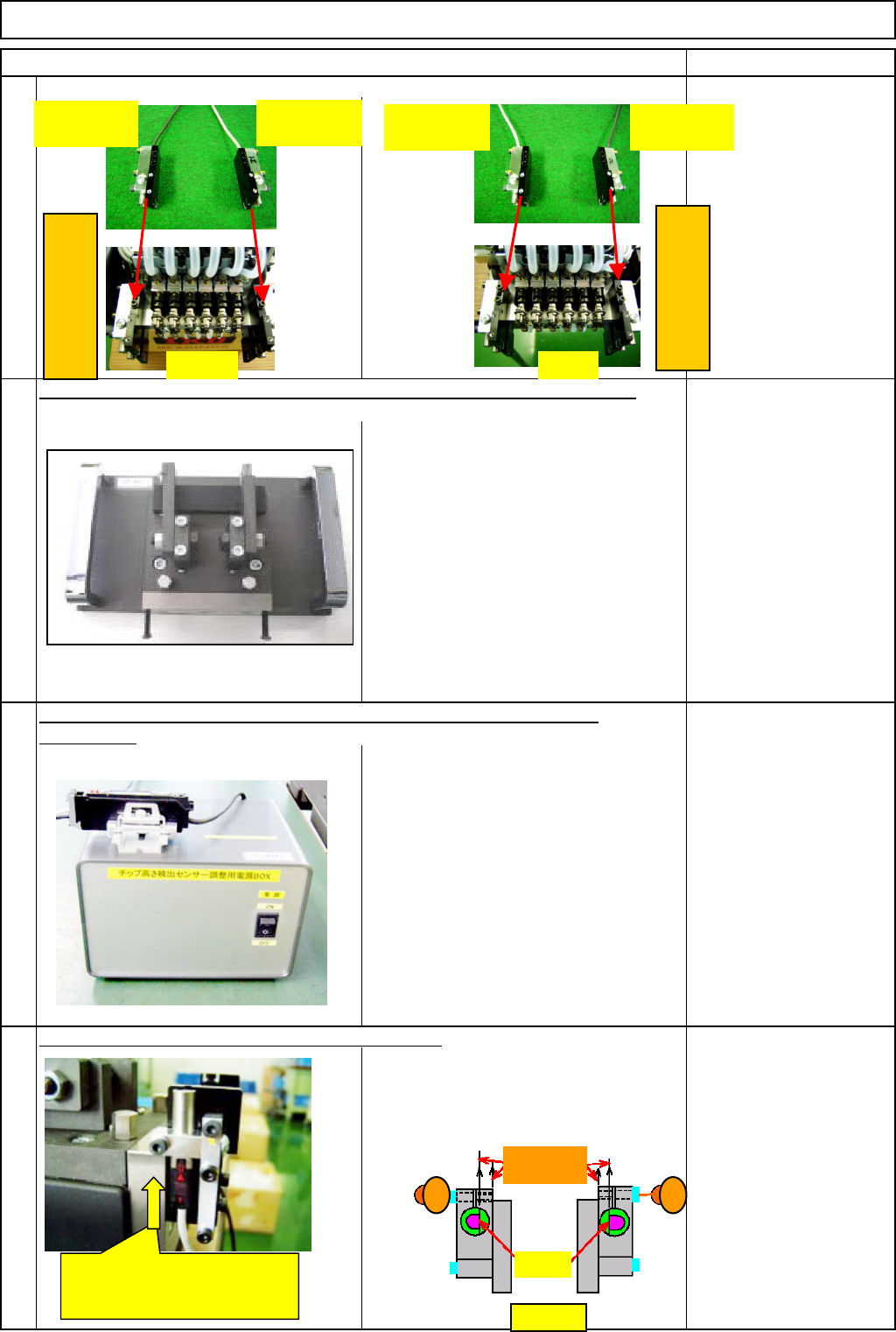
Position the D-shaped cut of each sensor
(light-emitting and -sensing) as shown in the
Figure 1 below. Insert each sensor from the
bottom up to the step and provisionally fix it
with the "M2.5×8L" bolt (1) or (2).
Prepare the component-height-detection-sensor-adjusting power source
FM-1853
(
1
)
.
Provisionally mount the new sensor. (front and rear)
25
26
Position the sensors correctly as shown below when installing them.
Prepare the component-thickness-sensor-light-axis-adjusting jig FM-1853(2).
Light-sensing
(Black cable)
Light-emitting
(Gray cable)
Left
(
Head-camera side
)
FRONT REAR
Insert the sensor from the bottom
up to the step. (The same to light-
emitting and -sensing sides)
Light-emitting
(Gray cable)
Light-sensing
(Black cable)
Right
(
Head-camera side
)
Figure 1
1 2
Should be
parallel
D-shaped
cu
t
EJM8A-E-SMA060402-A01-01
Page 6-4-2-8
Remark
Component-Thickness-Measuring Unit
Option Part and Accessory Replacement
Item
29
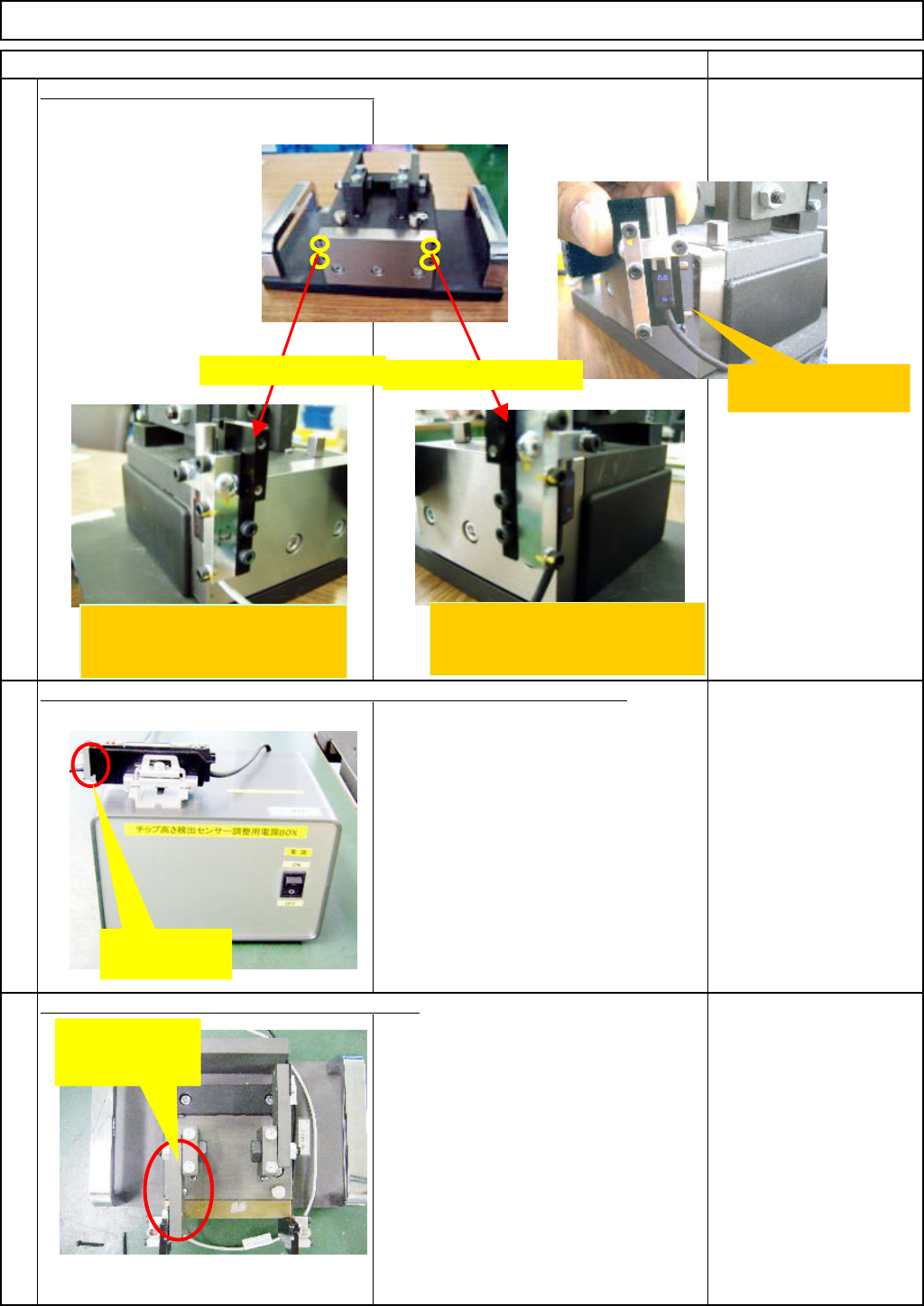
Switch on the jig. Check that a value is
displayed on the indicator of the sensor
amplifier.
FM-1853(1)
Component-height-
detection-sensor-
adjusting power source
30
Block the light by putting the jig plate
(with a filter) before the light-emitting
sensor (gray cable).
* Caution: If putting the plate before the
light-sensing sensor accidentally, the
glass will be broken.
FM-1853(2)
Component-thickness-
sensor-light-axis-
adjusting jig
Block the light-axis with the jig plate (with filter).
Insert the sensor connector into the jig-power-source-amplifier connector.
Mount the Front plates A and B on the jig.
28
Insert the dowel pin into
the jig hole.
Fix the light-emitting side
(the gray sensor cable) on the
left side.
Insert the
connector.
Block the light
with the light-
emitting plate.
Fix it on the left side
Fix it on the right side
Fix the light-sensing side
(the black sensor cable) on the
right side.
EJM8A-E-SMA060402-A01-01
Page 6-4-2-9
Remark
Component-Thickness-Measuring Unit
Option Part and Accessory Replacement
Item
Li
g
ht-axis ad
j
ustment -
(
1
)
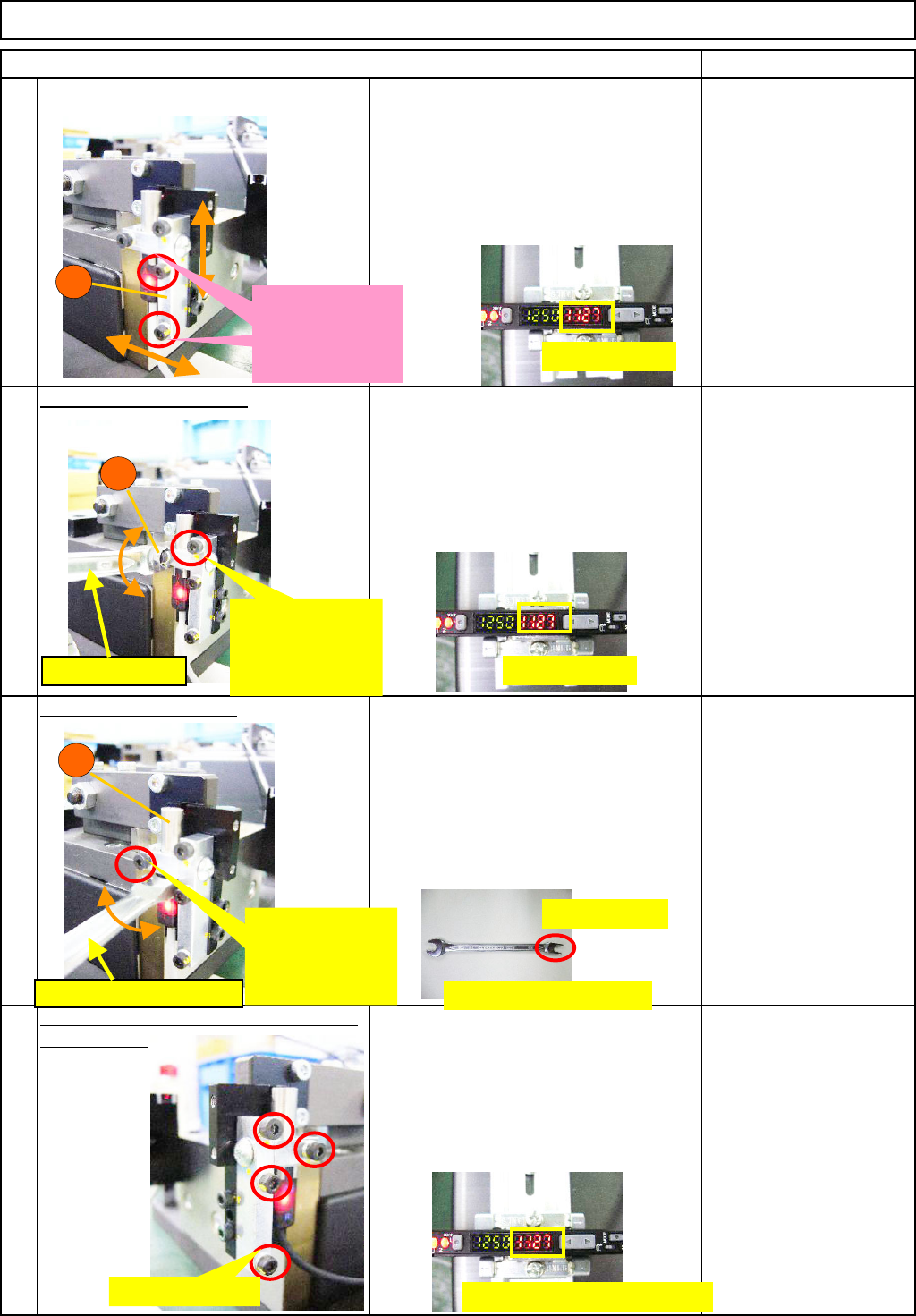
31
Provisionally fix the block (A) of the light-
emitting sensor (gray cable) loosely
enough to move the block by hand.
Moving the block in the arrow directions,
find a point at which the amplifier level
reaches maximum and provisionally fix
the block.
Allen key Long/Short
Li
g
ht-axis ad
j
ustment -
(
2
)
32
Provisionally fix the block (B) loosely
enough to move the block by turning it
with a wrench (size 6). Moving the block
in the arrow direction, find a point at
which the amplifier level reaches
maximum and provisionally fix the block.
Wrench size 6
Allen key Long/Short
Li
g
ht-axis ad
j
ustment
(
3
)
33
Provisionally fix the sensor (C) loosely
enough to move the sensor by turning it
with a special wrench. Moving the
sensor in the arrow direction, find a point
at which the amplifier level reaches
maximum and provisionally fix the
sensor.
Special wrench (size 6)
Allen key Long/Short
Securel
y
ti
g
hten the blocks A and B and
34
the sensor C.
Repeat "Light-axis adjustment - (1), (2)
or (3)" until the amplifier level reaches
1000 or more. Securely tighten the
blocks A and B, and the sensor C. After
securely tightening them, check the
amplifier level is 1000 or more.
Allen key Long/Short
A
滑り動く程度に
仮固定する
Provisionally
fix them loosely
enough to move
them by hand.
Amplifier level
B
Provisionally
fix it loosely
enough to move
it with a wrench.
Wrench (Size 6)
Provisionally
fix it loosely
enough to move
it with a wrench.
C
Special wrench (size 6)
Securely tighten
Amplifier level 1000 or more
Special wrench (size 6)
H-shaped cut
Amplifier level
EJM8A-E-SMA060402-A01-01
Page 6-4-2-10