CM602all_EJM8AESM_Service Manual.pdf - 第1046页
(Ex.) How to change "P A06," a 6-digit or more parameter, to "26214 4 Display "P A01" with the "MODE" switch. Display "P A06" with the "UP" switch. Press the "S…
MODE switch
changes display mode, and "Low" from/to "High."
UP switch
chan
g
es dis
p
la
y
and data.
DOWN switc
h
chan
g
es dis
p
la
y
and data.
SET switch
Determines dis
p
la
y
and data.
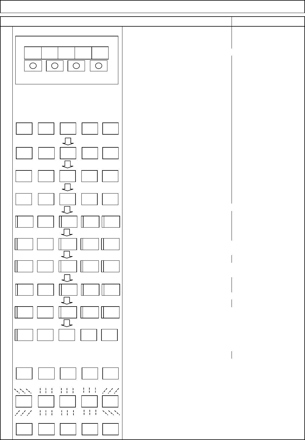
(1) Status indicator "C"
(2) Diagnosis "rd-oF"
(3) Alarm "AL --"
(4) Basic parameter "P A01"
(5) Gain and filter parameter "P b01"
(6) Expansion setting parameter "P C01"
(7) Input/output setting parameter "P d01"
(8) Another parameter 1 "P E01"
(9) Another parameter 2 "P F01"
(10) Another parameter 3 "P o01"
Caution
To check or change a parameter, display (4) to (7).
Before changing the parameter after driver replacement,
set PA19 first.
For parameter values to be set, see the parameter list in following
pages. (8) to (10) are reserved for setting by the manufacturer.
How to check or change the parameters.
• Basic parameter: "P A01" to "P A19"
• Gain and filter parameter: "P b01" to "P b45"
• Expansion setting parameter: "P C01" to "P C50"
• Input/output setting parameter: "P d01" to "P d30"
• Another parameter 1: "P E01" to "P E40"
• Another parameter 2: "P F01" to "P F20"
• Another parameter 3: "P o01" to "P o08"
• The left shows the indication with
power ON
Pressing the "MODE" switch changes
mode as shown in (1) to (7) below.
(Ex.) How to check or change the basic parameters.
Display "P A01" with the mode switch.
Pressing the "UP" switch changes from "P A01," "P A02" to "P A03."
Pressing the "DOWN" switch changes the reading in reverse order.
Change "P A01." With "P A01" displayed, press the "SET" switch twice.
The preset parameter value blinks. The value should be 0. If not, change
that value to 0, pressing the "UP" and "DOWN" buttons as necessary.
When the value is blinking, it can be changed. After changing the set value,
pressing the "SET" switch determines the new setting. To move on to the
next parameter, press the "UP" or "DOWN" switch.
Item Remark
12
• Driver operation panel
Tray Direct Tray
Driver LED indicator
ドライバ操作部
MITSUBISHI
MR-J3
MODE UP DOWN SET
LED表示部
C
r - o Fd
A - -L
P A 0 1
P b 0 1
P C 0 1
P d 0
1
P A 0 1
0 0 00
P A 0 1
P E 0 1
P F 0 1
P o 0
1
Driver operation panel
MITSUBISHI
MR-J3
MODE UP DOWN SET
LED indicators
C
r - o Fd
A - -L
P A 0 1
P b 0 1
P C 0 1
P d 0 1
P A 0 1
0 0 00
P A 0 1
P E 0 1
P F 0 1
P o 0 1
EJM8A-E-SMA070209-A01-00
Page 7-2-9-5
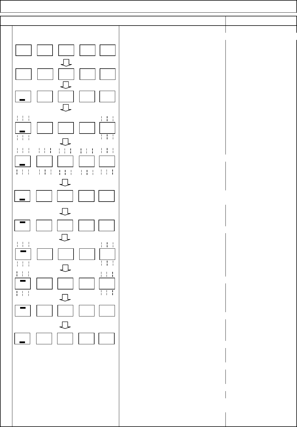
(Ex.) How to change "P A06," a 6-digit or more parameter, to "26214
4
Display "P A01" with the "MODE" switch.
Display "P A06" with the "UP" switch.
Press the "SET" switch once.
"_ 1" is displayed.
Press the "SET" switch once.
"_ 1" is blinked.
Change the value to "_2144" with the "UP" or the "DOWN" switch.
After changing the value, press the "SET" switch once.
Blinking stops and the set value is determined.
Press the "MODE" switch once.
The setting mode for the first digit from the top, "- 0" is displayed.
Press the "SET" switch once.
"- 0" is blinked.
Change the value to "- 26" with the "UP" or the "DOWN" switch.
Press the "SET" switch once.
Blinking stops and the set value is determined.
The lowest 4-digit setting mode is returned.
To move on to the next parameter,
press the "UP" and the "DOWN" switches.
Caution
To make the changed value effective, turn off and turn on the power.
Taking the same procedures, set and check the gain and filter
parameters, the expansion parameter, and input/output setting
parameters.
Press the "SET" switch once.
Direct Tray
Item Remark
Tray
Driver LED indicator
P A 0 1
P A 0 6
1
1
1 4 42
1 4 42
0
0
2 6
2 6
1 4 42
P A 0 1
P A 0 6
1
1
1 4 42
1 4 42
0
0
2 6
2 6
1 4 42
EJM8A-E-SMA070209-A01-00
Page 7-2-9-6

Basic
p
arameters
Name
PA01 Control mode 0 0
PA02 Regenerative brake option 0 0
PA03 Absolute position detection system 0 0
PA04 Function selection A-1 1 0
PA05 No. of command input pulses per rotation 0 0
PA06 Electronic gear numerator
PA07 Electronic gear denominator
PA08 Auto tuning mode 1 1
PA09 Auto tuning response 23 23
PA10 In-position range 4 7
PA11 Forward rotation torque limit 100 100
PA12 Reverse rotation torque limit 100 100
PA13 Command pulse input form 10 0
PA14 Rotation direction selection 1 1
PA15 Encoder output pulse
PA16 For manufacturer setting 0 0
PA17 For manufacturer setting 0 0
PA18 For manufacturer setting 0 0
PA19 Parameter block 00AB 00AB
Gain and filter parameters
Name
PB01 Adaptive tuning mode (Adaptive filter II) 2 2
PB02
Vibration suppression control tuning mode (Advanced vibration suppression control) 00
PB03
Position command acceleration/deceleration time constant (Smoothing) 33
PB04 Feed forward gain 0 0
PB05 For manufacturer setting 500 500
PB06 Ratio of load inertial to servo motor inertia 7 8.9
PB07 Model control gain 92 62
PB08 Position control gain 139 93
PB09 Speed control gain
PB10 Speed integral compensation 8.9 13
PB11 Speed differential compensation 980 980
PB12 For manufacturer setting 0 0
PB13 Machine resonance suppression filter 1 540
PB14 Notch shape selection 1 0 210
PB15 Machine resonance suppression filter 2
PB16 Notch shape selection 2 0 0
PB17 For manufacturer setting 101 101
PB18 Low-pass filter setting
PB19 Vibration suppression control Vibration frequency setting 100 100
PB20 Vibration suppression control Resonance frequency setting 100 100
PB21 For manufacturer setting 0 0
PB22 For manufacturer setting 0 0
PB23 Low-pass filter selection 0 0
PB24 Fine vibration suppression control selection 0 0
PB25 Function selection B-1 0 0
PB26 Gain change selection 0 0
PB27 Gain change conditions 10 10
PB28 Gain change Time constant 1 1
PB29 Gain change Ratio of load inertial to servo motor inertia 7 7
PB30 Gain change Position control gain 37 37
PB31 Gain change Speed control gain 823 823
PB32 Gain change Speed integral compensation 34 34
TL-axis TP-axis
TL-axis TP-axis
4000 4000
1500
45004500
3690 3141
2956 2484
262144
3200
262144
3682
No.
Tray Direct Tray
Lift-axis (TL) and Extension-axis (TP) Parameter List
No.
EJM8A-E-SMA070209-A01-00
Page 7-2-9-7