CM602all_EJM8AESM_Service Manual.pdf - 第429页
Machinery Part Replacement Remarks L ight Transfer-Head Assembly (8-nozzle type ) Item Remove the motor holdin g screws. Allen key 3 mm Screw M4x16L 2 pcs. Remove the motor from the plate. Z-axis motor removed from the m…
Machinery Part Replacement
Remarks
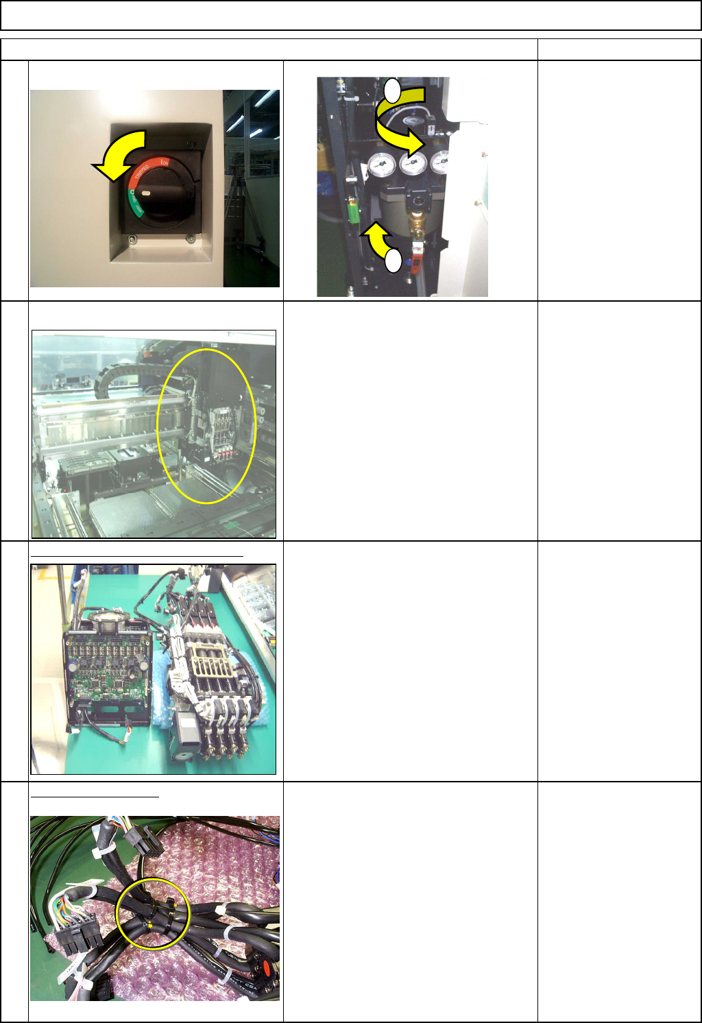
Switch off the main power and air supply.
Remove the head assembly.
Refer to "Transfer Head Replacement." Section 5-3-1
Separate the Z unit from the board.
Refer to "Separating the Z-Unit from the
Board."
Left: Z-axis controlling board
Right: Z-axis drive unit
Section 5-3-14
Cut off the cable ties.
Nipper
L
ight Transfer-Head Assembly (8-nozzle type
)
Item
3
4
1
2
1
2
EJM8A-E-SMA050306-A01-00
Page 5-3-6-2
Machinery Part Replacement
Remarks
L
ight Transfer-Head Assembly (8-nozzle type
)
Item
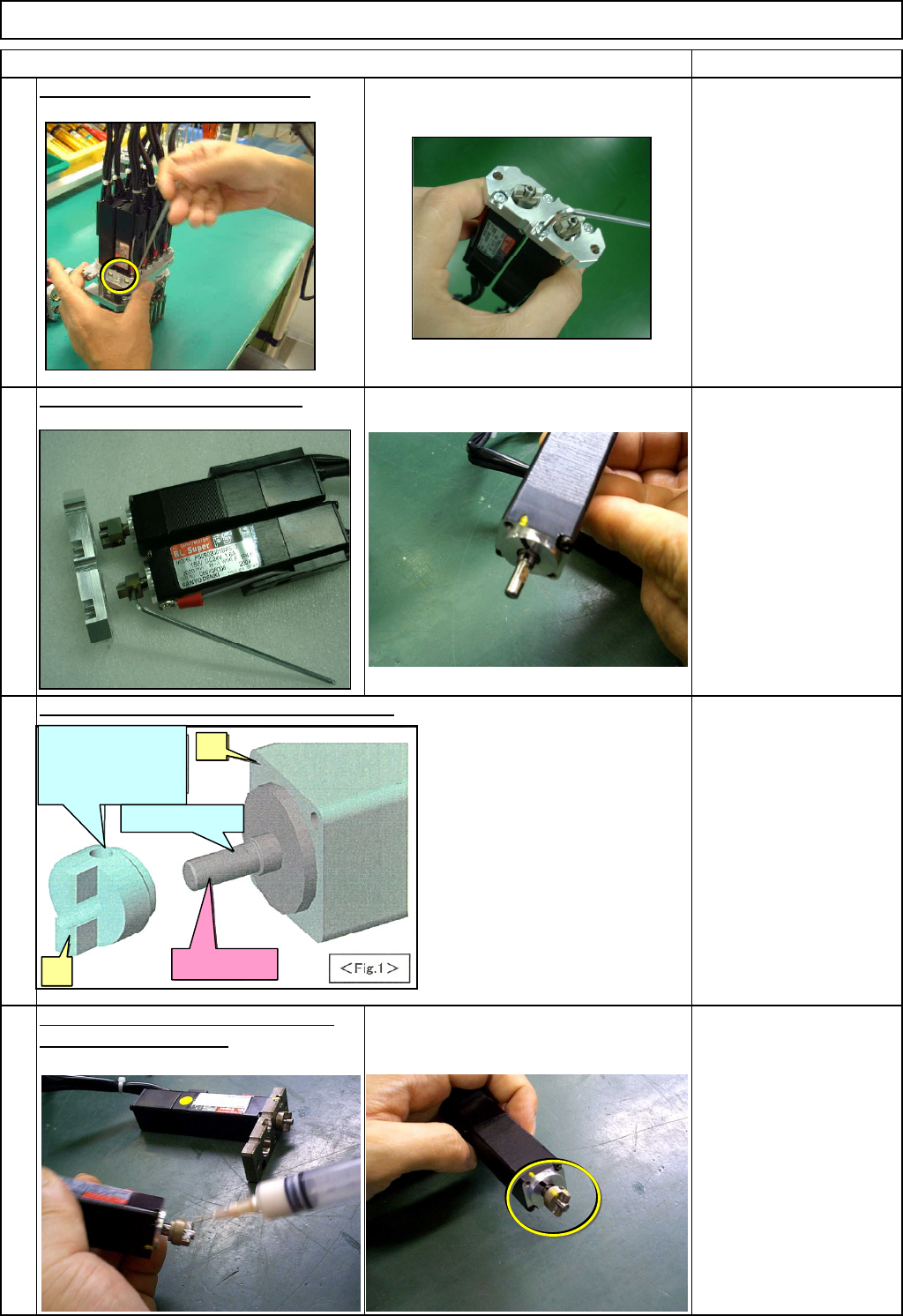
Remove the motor holdin
g
screws.
Allen key 3 mm
Screw M4x16L 2 pcs.
Remove the motor from the plate.
Z-axis motor removed from the machine Allen key 2.5 mm
Screw M3x8L 2 pcs.
Magic marker
A
ppl
y
a small amount of
g
rease to the
Tighten the set-screw, aligning the
joint of the Z-axis motor.
set-screw hole with the D-shaped cut
on the motor shaft.
Allen key 2 mm
MP Grease 2S
Relationship of motor shaft and joint positions
8
5
6
7
D: Align the set-screw
hole of (2) with the D-
shaped cut on (1)
(2)
(1)
C: D-shaped cut
Motor shaft
EJM8A-E-SMA050306-A01-00
Page 5-3-6-3
Machinery Part Replacement
Remarks
L
ight Transfer-Head Assembly (8-nozzle type
)
Item
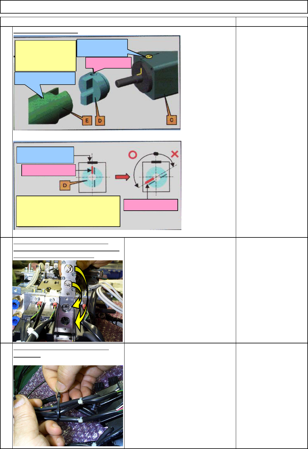
How to install the motor:
Install the Z-axis motor, positioning the
set-screw hole of D above 90 degrees away
from the mark on the motor shaft.
・Raise the ball screw almost to
maximum.
・The set-screw hole of "D" above should
be positioned more than 90 degrees
away from the mark on the motor. The
hole should be displaced
counterclockwise when seen from above.
Secure the Z-axis motor cables with
cable ties. Nipper
Cable tie 100mm
11
10
9
Mark on "C" should be
more than 90 degrees
away from the set-screw
hole of "D."
Raise it almost to
maximum.
Mark put when "C"
was assembled.
Set-screw hole
Mark put when "C"
was assembled.
Set-screw of "D"
Set-screw of "D"
Mark on "C" should be more than 90
degrees away from the set-screw hole
of "D."
EJM8A-E-SMA050306-A01-00
Page 5-3-6-4