CM602all_EJM8AESM_Service Manual.pdf - 第105页
* Check the attachment and detachment of metal fittings for transportation using this list. Once installation is completed, keep this list in the shipment inspection list file. CM602L No Attach Detach 1 X-axis table lock…
Inspected on Month Date Year
Installation Check List (4/4) Document Ver. 1.00
Customer name:
Target model: Modular CM602-L
Production code:
Software Ver.
1. Purpose: Check that there is no problem with M/C operation by checking the following items at the time of installation.
2. Judgment: Circle the "OK" for each column after inspection or adjustment check.
Serial No. Serial No.
No. Checking points
Check result Check result
29 Carry out Pickup position and Pickup height teaching.
(High-speed 130 nozzle, Multi-functional 1003 nozzle, Pickup jig)
30
Check the tape cutters on all stages for cutting.
31
Check the nozzle changer for operation. (10 min. for each stages)
32
Check board transfer. (User's boards), Check signal to/from non-Panasonic M/C.
33
Check board transfer. (User's boards), Check signal to/from non-Panasonic M/C.
34
35 Save the machine parameters.
(Be sure to save them when delivering the machine to the customer.)
36 Check that the machine foot plates are seated securely. (6 plates)
Check, hitting the foot plates lightly with a 46 wrench.
1KJZ 1KJZ
1 Check voltage. DC5V V1 - G1 (5.05 + 0.03V)
DC12V V2 - G2 (12.00 +/- 0.1V)
DC24V V4 - G4 (24.00 - 24.30V)
2 Check ST40 operation.
3
4
5
6
7
8 Check CM602 and ST40S for operation. (Test run: 15 min.)
OK
OKOK
ST40S-20 (Option)
Measured
valu
e
Measured
valu
e
Measured
valu
e
Measured
valu
e
Measured
valu
e
Measured
valu
e
( V)
( V)
( V)
OK
Serial No. Serial No.
OK
OK
OK
OK
OK
OK
OK OK
( V)
( V)
( V)
OK
OK
OK
OK
OK
OK OK
OK
OK OK
OK
Sign the Delivery label of the machine. (Representative's name)
Check position of pickup and delivery. (Shuttle and tray teaching)
Secure the CM602 to ST40 connection cable. Do not lose the short plug.
OK
OK
OK
OK
OK
OK
OK
Check the tray stops when the emergency stop switch is pressed.
The tray should not move with the servo switch off.
Check warning when the magazine door, the supply section or the pickup section is op
e
With the shutter closed, gap between palette and shutter should be 0.1 to 0.2 mm.
Customer's copy
EJM8A-E-SMA020103-A01-00
Panasonic Factory Solutions Co., Ltd.
Page 2-1-3-36
F3A0016-03A
* Check the attachment and detachment of metal fittings for transportation using this list.
Once installation is completed, keep this list in the shipment inspection list file.
CM602L
No
Attach Detach
1 X-axis table locking metal Metal fitting x 4
fitting M6 -18 bolt - 2 x 4
2 Y-axis table locking metal Metal fitting x 4
fitting (R) M6-18 boltー2 x 4
3 Y-axis table locking metal Metal fitting x 4
fitting (L) M6-18 bolt - 2 x 4
4 Batch Exchange Cart table Metal fitting x 8
locking metal fitting M5-12 bolt+AWー4×4
(Feeder change cart)
Installation Machine Installation
2-1-4 Holding Metal Brackets
Name of metal fittings Parts/Bolt size/Qty
EJM8A-E-SMA020104-A01-00
Page 2-1-4-1
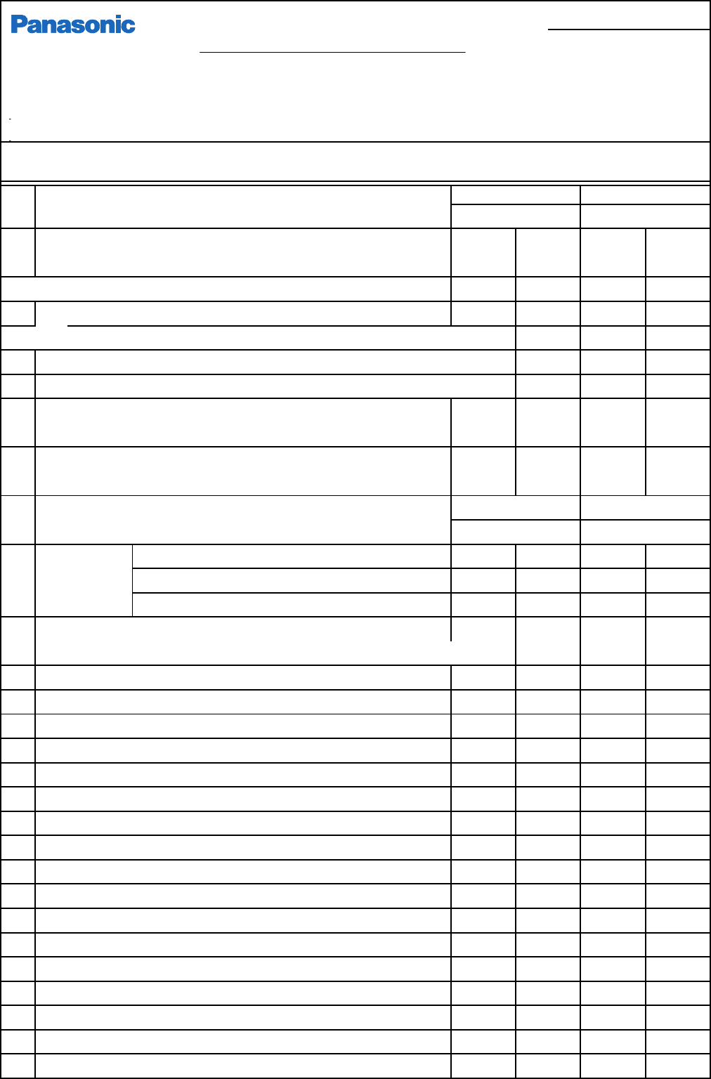
ST40-20
No
Attach Detach
1 X-axis table locking metal fitting Metal fitting×1
M4-10 boltー4
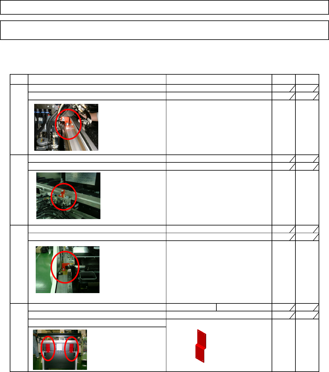
2 Z-axis table locking metal fitting Metal fitting x 2
M3-8 bolt - E382x2
3 Lifter axis locking metal fitting Metal fitting
M5-12 bolt×4
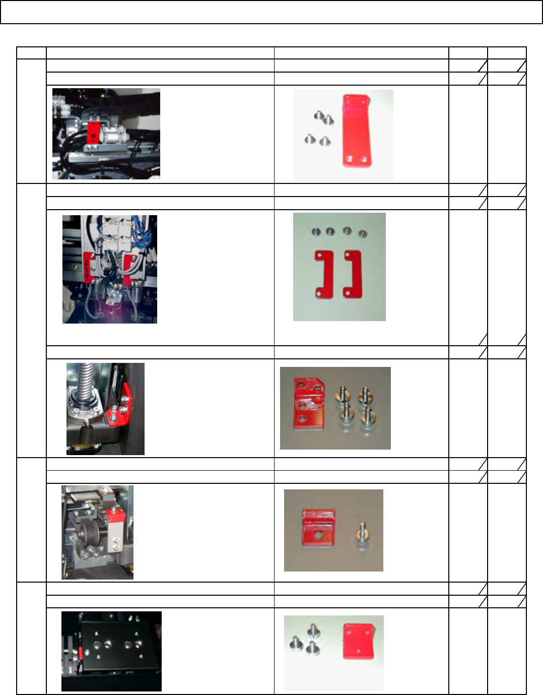
4 Pallet drawing unit locking metal fitting Metal fitting
M3 -10 bolt x 1
5 Conveyor locking metal fitting Metal fitting x 1
M4 - 10 bolt x 3
Name of metal fittings Parts/Bolt size/Qty
Installation Machine Installation
EJM8A-E-SMA020104-A01-00
Page 2-1-4-2