CM602all_EJM8AESM_Service Manual.pdf - 第69页
Caution 1. Be sure to turn off the servo switch before working on the machine. Caution 2. When inspection is carried out by two or more persons, give appropriate warning to each other. Caution 3. Watch your head while wo…
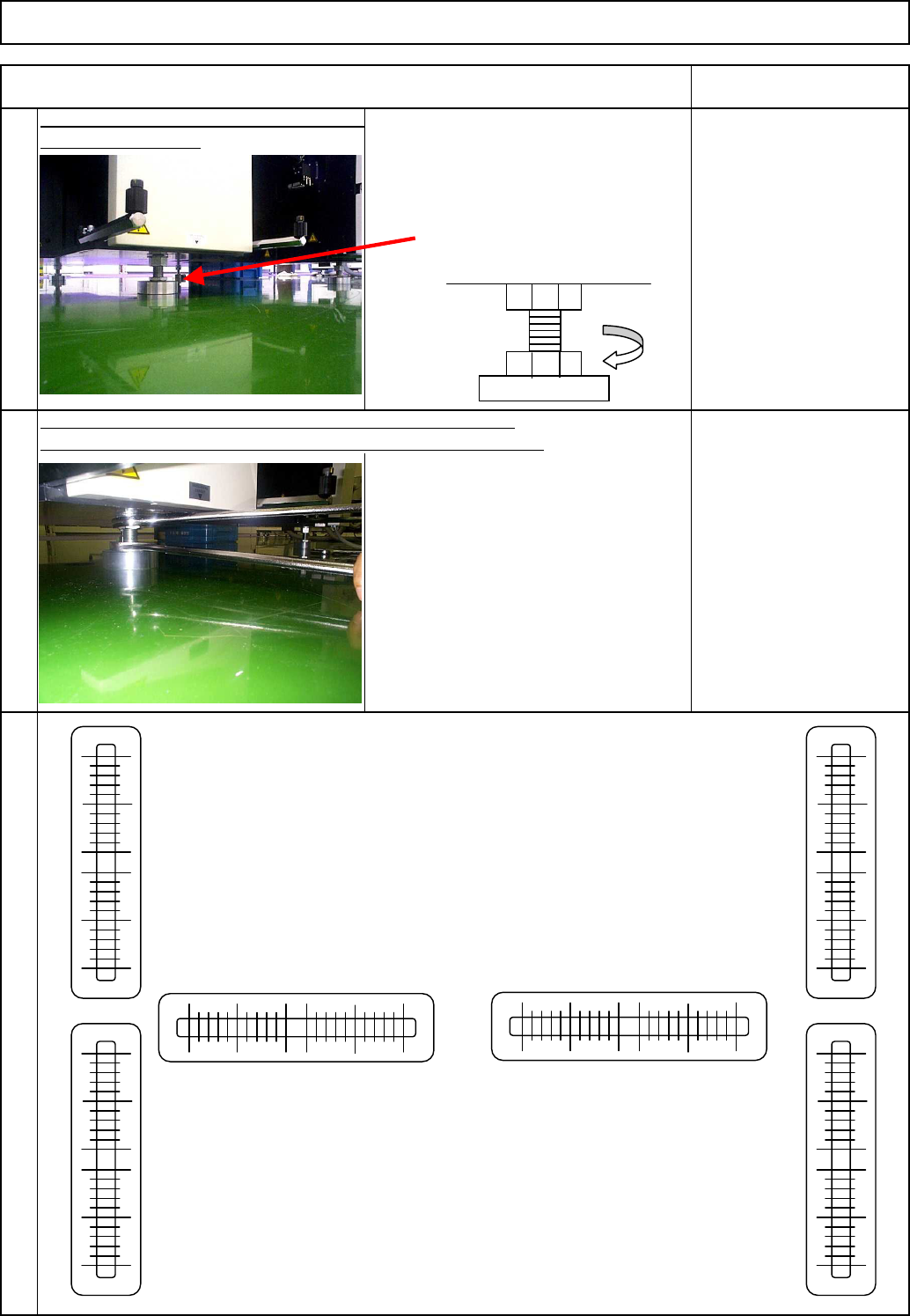
Lower the Adjusting Bolts B and E to the
floor so that the feet of the bolts do not
move. Rotate the bolts 45 degrees and
lock the lock nuts.
Once adjustment has been complete, lock the adjusting bolts.
Put a mark on the lock nut. Check that the bolt is seated securely.
7
Lower the center adjusting bolt to the floor
Tools and Specification
Check the levelness.
Level
Wrench 45 mm
Spec.: 0.04 mm or less
45°
9
8
Wrench 45 mm 2 pcs.
Setting Machine Setting
Item Remarks
(1)
(3)
(2)
(4)
(5)
(6)
EJM8A-E-SMA020102-A01-00
Page 2-1-2-6
Caution 1. Be sure to turn off the servo switch before working on the machine.
Caution 2. When inspection is carried out by two or more persons, give appropriate
warning to each other.
Caution 3. Watch your head while working on the machine.
Caution 4. After finishing the inspection of the delivery installation procedures, carry out
delivery inspection.
Caution 5. Slowly move up and down the voltage adjustment volume of the DC electric
source. Suddenly moving it up may break the board.
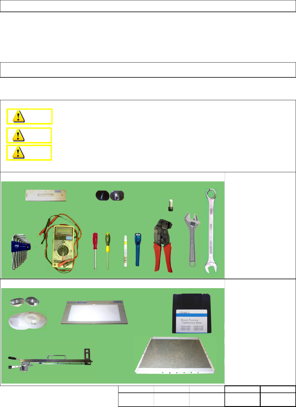
・Level
・Nozzle
・Allen key
・Sleeve
・Phillips screwdriver
・Flat-head screwdriver
・Adjustable wrench
・Combination wrench
・Pen light
・Magic marker
・Clamper
Tester
・Nozzle changer jig
・1005 and 0603 R components
・Pickup position teaching jig
・Placement correcting
position teaching jig.
・Placement correcting
position teaching data (FD)
・Nozzle 110 24 pcs.
・ Tape Feeder 0.5P 4 pcs.
min.
・This section describes the procedures for inspecting the equipment when it is delivered.
・Tools
・Jigs
min.
kgs
0
Installation Machine Installation
2-1-3 Delivery Inspection
Part weight
Teaching
Assembly/AdjustmentRemoval/Disassembly
min.min.
Danger
Warning
Caution
EJM8A-E-SMA020103-A01-00 Page 2-1-3-1
[Power cables recommended] * Power cables: option
For overseas use, 5-core cable AWG#12
is recommended.
For domestic use, use 4-core cable
AWG#10 by PFSC for domestic use.
[Electric source conditions]
Frequency: 50/60Hz±5%
Rated capacity: 2.5KVA
Primary tap change support voltage
←Dom. & Overseas (Except for EU)
← Domestic
← EU (400V)
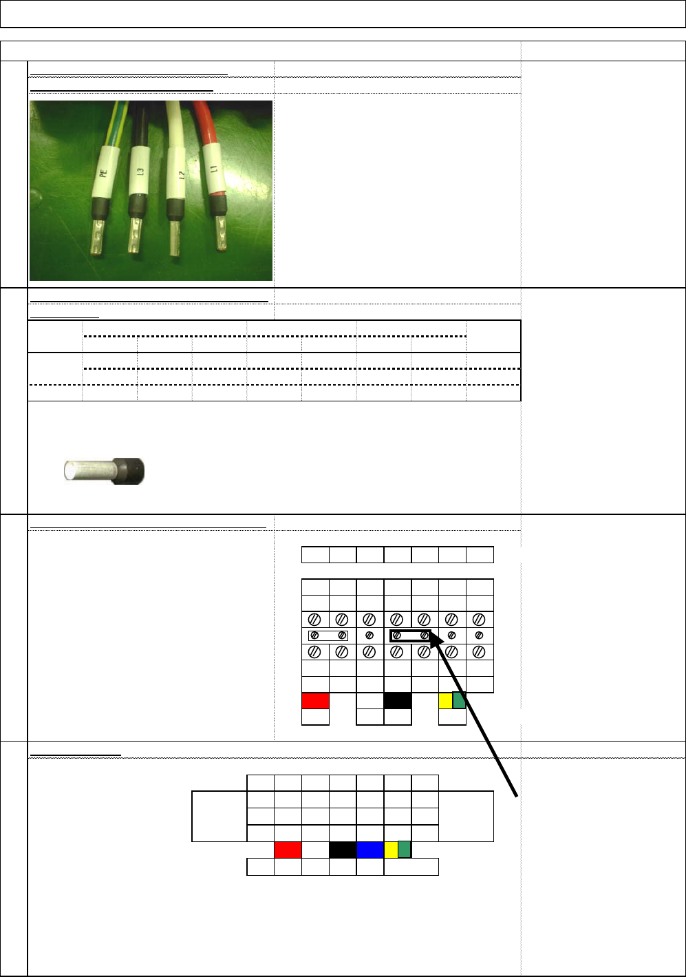
[Cable sleeve]
Fit a desired sleeve onto the end of the cable
(Cables that are caulked and are secured with sleeves □C × AWG□
are shown in Step 1) No. of core Size
L1 L1 L2 L3 N E E
←Secondary-side cables
L1 L1 L2 L3 N E E
L1 L1 L2 L3 N PE =
L1 L2 L3 PE
←
Primar
y
-side cable
s
. "5C" is used in the EU countries.
L1 (red)
L2 (white)
L1 L1 L2 L3 N
L3 (black)
N (blue)
L1 L1 L2 L3 N PE PE
PE (green/yellow)
red
white black
blue gr/yel
↑Primary-side
cables
When using 5C, place the cable as shown above:
Note for cabling
Refer to "Note for cabling"
placed under the terminal
block.
* Important
• When connecting the neutral
(N) line, remove the short bar.
Otherwise, a short-circuit will
occur.
* Reference
UL/CE standard cables are shown below:
Outside mm
Thick mm
3
When cabling, be careful of the followings:
No.of cores
Conductor
2
Size AWG
Qty/mm
Installation
1
(4C for 200V are shown below:)
480/420/400/380/220/200V
Tighten the power cable terminals.
Item
Machine Installation
Remark
4
Weight
(approx.)
K
g
/Km
Heat-proof vinyl insulation
Oil & heat-proof flexible vinyl sheath
Thick mm
Outside mmOutside mm
400
5C
12
66/0.254
10
104/0.254
4C
3.1 520
2.4
■When connecting the cable, refer to the
illustration at right. (Except for Europe)
■When connecting, use copper wires
only.
■Use the terminal tightening tool that
came with the machine.
(Tightening torque: Refer to Step 1.)
18.9
17.31.25 4.9 2.65
Sign description
1.25 5.6 2.65
[Tightening torque spec.]
Terminal tightening torque
0.8 N.m to .16 N.m
[Tools]
Torque wrench
If not available:
Flat-head screwdriver that
came with the machine
EJM8A-E-SMA020103-A01-00 Page 2-1-3-2