CM602all_EJM8AESM_Service Manual.pdf - 第617页
Machinery Part Replacement Remark 12-Nozzle Head Unit Item Shaft assembl y ( 4 ) Shaft assembl y ( 5 ) Shaft insertion ( 1 ) 18 15 17 16 5. Remove the jig. Be careful that C and the C packings are not removed from B and …
Machinery Part Replacement
Remark
12-Nozzle Head Unit
Item
Shaft assembl
y
(
1
)
Shaft assembl
y
(
2
)
Jig (FM-1737)
Barrierta grease
Shaft assembl
y
(
3
)
12
14
13
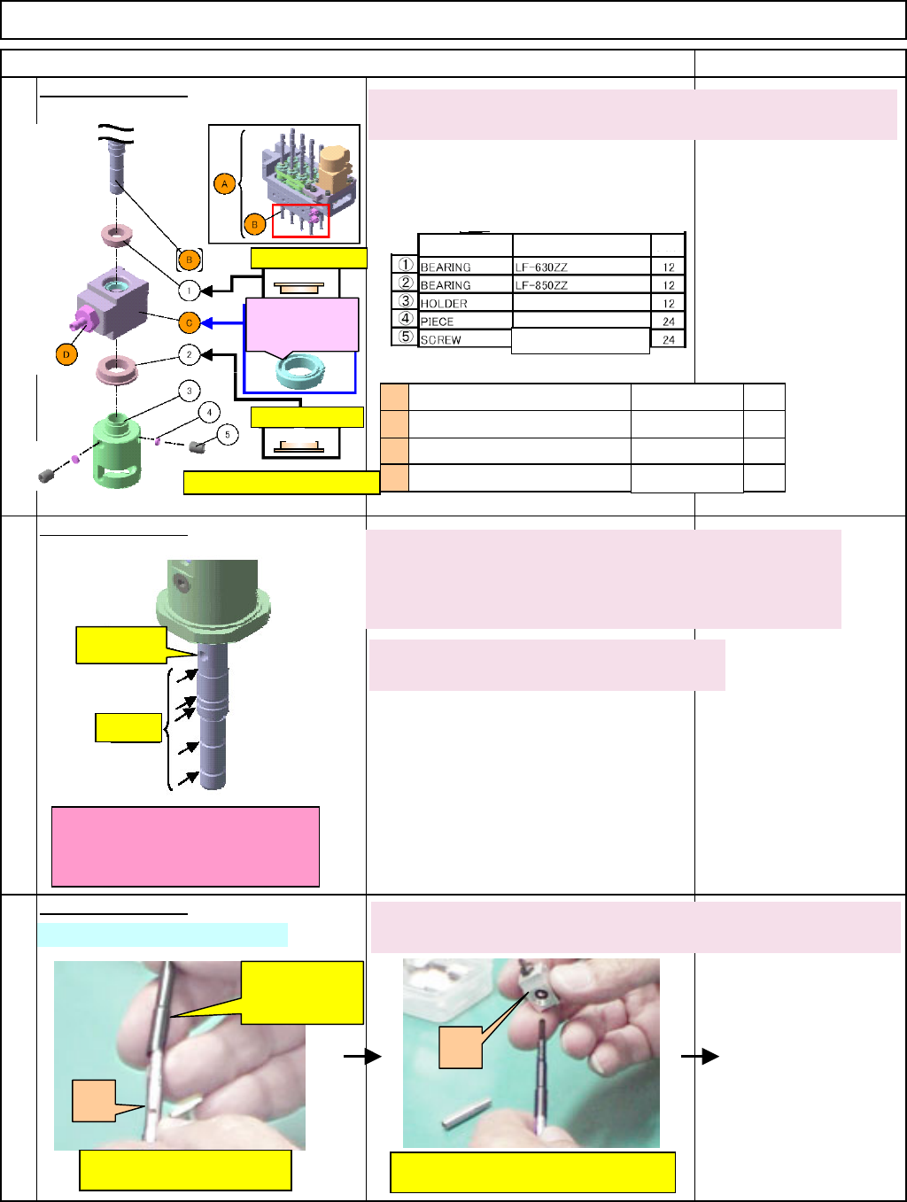
1. Insert the spline shaft (B) into (1).
The convex section should face downwards. See the left figure.
Uppe
r
(1): Check direction.
C: Groove surface of
packing should be
outside of A. (Both
sides
)
上
(2): Check direction.
* Assembly points: Total of 12
Part name Model
Qty
Hexagon socket setscrew
M2.5x3L
2. Put the insertion jig (FM-1737) on the spline shaft (B).
Check the insertion jig (See Figure 14.) covers the
groove section and the vacuum hole of B (See Figure 12.)
3. Apply grease to the insertion jig slightly
* as lubricator when the jig is removed later.
Vacuum
hole
Groove
* Check the insertion jig covers the
vacuum hole and the groove of B
when the jig is put on the shaft.
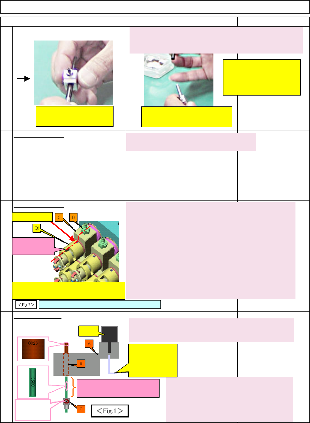
4. Put the spline shaft (B) into the spline housing (C). The joint (D)
should face outwards. See the left and below pictures.
Spline-shaft-insertion
Insertion jig
(provisional
one
)
I. Put B into the jig.
II. Put "B" and the jig into "C."
B
C
D
C
B
A
Joint
Ball spline (Spline shaft)
Spline housing
θ
-axis unit
* C
* P201
(12)
12
(12)
12
Uppe
r
EJM8A-E-SMA051002-A01-00
Page 5-10-2-5
Machinery Part Replacement
Remark
12-Nozzle Head Unit
Item
Shaft assembl
y
(
4
)
Shaft assembl
y
(
5
)
Shaft insertion
(
1
)
18
15
17
16
5. Remove the jig.
Be careful that C and the C packings are not removed from B
and that the spline shaft is not broken when removing the jig.
* Machine is different, but
what to do is the same.
III. "B" + jig though "C"
IV. Remove the jig, being careful
not to let C separate from B
6. Insert (3) into (2).
The convex side of (3) should face upwards.
7. Insert the spline shaft (B) into the (2) and (3) assembled in
Step 6.
Be careful of direction of assembly seeing the left figure
when
inserting the shaft.
8. Fix (3) onto the spline shaft (B) with (4) and (5).
Push (3) until C goes into the step section of B (no gap
between C and B). Provisionally fix (3), aligning C with D as
shown at left.
* There should be no gap between B, C and (3).
* Be careful that (4) is straightened and that ⑤ is inserted
fully when fixing (3).
③ hollowset hole
Installing guide
(Vertical groove)
Provisionally fix (3) so that the installing guide and
the hollowset screw of (3) are aligned with the joint
D.
* Figure of nozzle installed. What to do is the same.
1. The code of the bearing case (B) should be the same as
that of the spline housing (C).
2. The code of the bearing case (B) should
face outwards. Put an Allen key into the
adjusting screw at the end of the motor shaft.
Turn the shaft until the code of (B) faces
outwards.
Motor
A
llen key to turn the
baring case (B)
(Do not use a ball-
point Allen key; it can
be slide easily.)
* Apply grease to the jig.
The groove should be filled with
grease.
The joint hole
should face
outwards.
EJM8A-E-SMA051002-A01-00
Page 5-10-2-6
Machinery Part Replacement
Remark
12-Nozzle Head Unit
Item
Shaft insertion
(
2
)
19
Shaft insertion
(
3
)
20
A
ssemblin
g
the
p
eri
p
heral section
(
1
)
21
22
3. The shaft code of the spline housing (C) should face
outwards.
Make the code of (C) face outwards so that it faces in the
same direction as that of the bearing case (B).
4. Apply grease to the spline housing (C) slightly. The shaft
groove should be filled with grease. (See Figure 18.)
Bearing ball
A
lign it with the shaft
groove. Insert the shaft
into B.
5. Insert the bearing case (B) into the spline housing (C)
lightly.
Position the mouth of the joint (with C assembled)
outwards, and insert (B) into (C), aligning the bearing balls in
the (B) shaft with the groove of (C). Be careful no to let the
bearing ball jump out.
6. Repeat Steps 1 to 4 until the total of twelve (12)
kits are created.
Outwards
Inwards
Apply grease to the
both ends of the spring
(2).
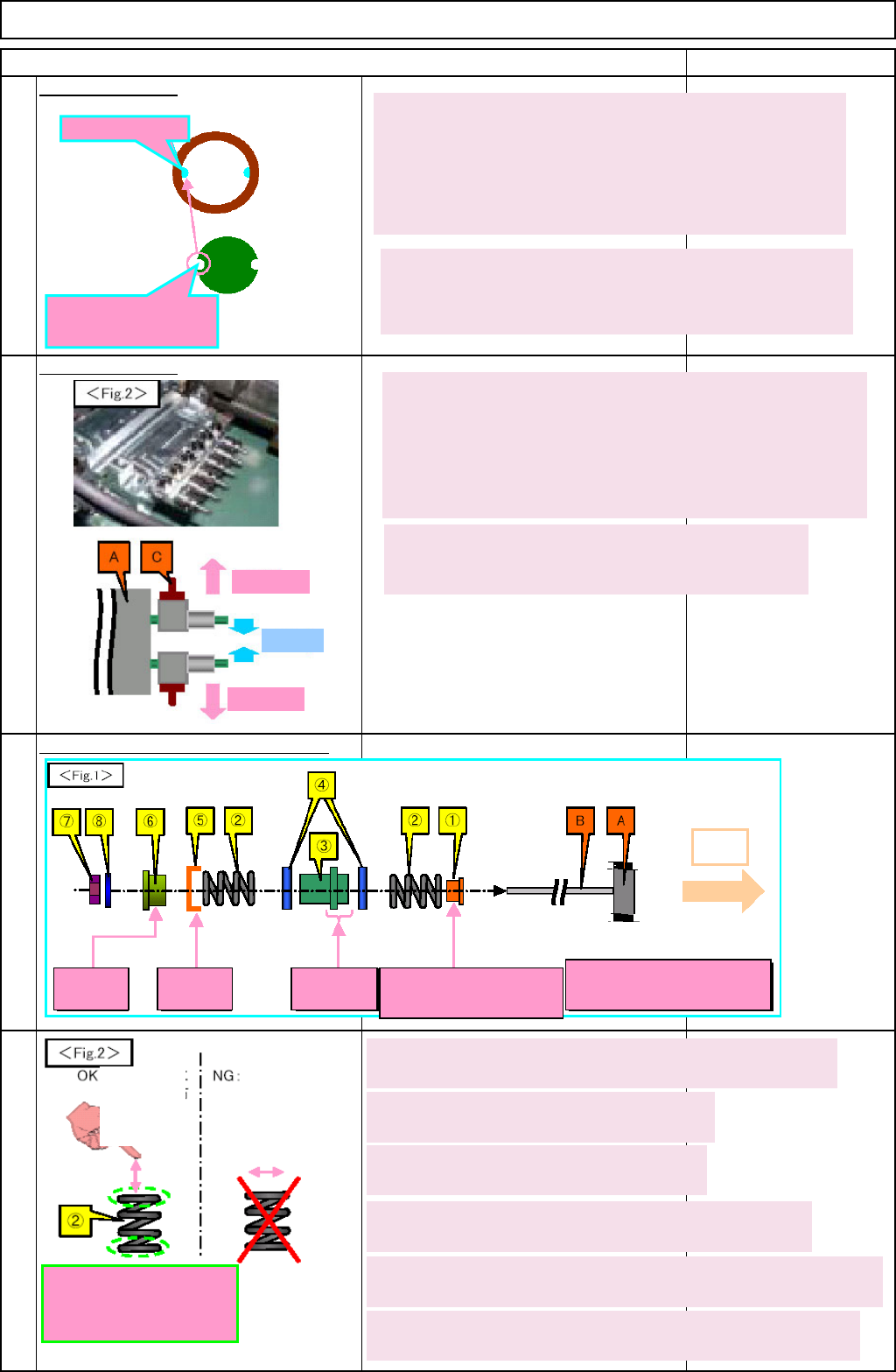
1. Insert the spline shaft (B) (with A assembled) through (1)
Be careful of the direction of (1).
2 . Apply grease to both ends of (2) slightly.
The total of 24
3. Insert the spline shaft (B) through (2).
Insert B into greased (2). The total of 12
A
pply grease to
the upper and
lower surfaces
of the spring.
Spread the
grease
horizontally.
4. Insert the spline shaft (B) through (3) and (4).
(3) should be between (4)s. Check the direction of (3).
5. Insert the spline shaft (B) through (2) and (5).
Insert B through greased (2) and (5). Check the direction of (5).
6. Join (6) to the kit above (in Step 5) with (7) and (8).
Assembling torque : 108 +/-9 N•cm. Check the direction of (6).
Convex
side: A
Concave
side: A
Shorter: A Convex side: Opposite of
A
* Be careful of direction
of cegh
A
Outwards
EJM8A-E-SMA051002-A01-00
Page 5-10-2-7