CM602all_EJM8AESM_Service Manual.pdf - 第162页
Maintenance Adjustment Main Body Beam Remarks Item Put back the sensor covers. Phillips screwdriver #2 Screw M4 8 pcs. Put back the feeder cover. Phillips screwdriver #2 Screw M4 2 pcs. 10 9 EJM8A-E-SMA040107-A01-00 Page…
Maintenance Adjustment Main Body Beam
Remarks
Item
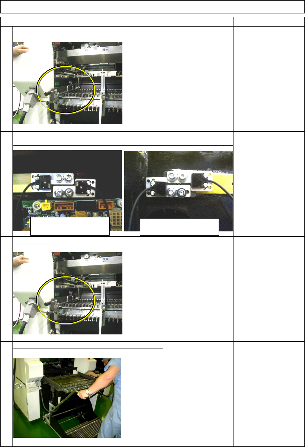
Set the tape float sensor adjusting jig.
Precesely position the left and the right
sensors.
Tape Float Sensor
Adjusting Jig
Loosen the sensor holding screws.
Allen key 2.5 mm
Screw M3 8 pcs.
Remove the jig.
Tape Float Sensor
Adjusting jig
Once the adjustment has been finished, remove the cart.
Refer to "Feeder Gang Exchange Cart
Installation and Removal."
Since the feeder covers are left removed,
block the light beam of "Tape Float
Sensor 1" with tape or equivalent.
Once the cart is removed, remove the
tape.
Section 5-8-1
Tape
Precisely position the sensor so that the light axis passes through the hole of the jig.
6
7
5
8
Light-sensing device
(on the left side)
Light-emitting device
(on the right side)
EJM8A-E-SMA040107-A01-00
Page 4-1-7-3
Maintenance Adjustment Main Body Beam
Remarks
Item
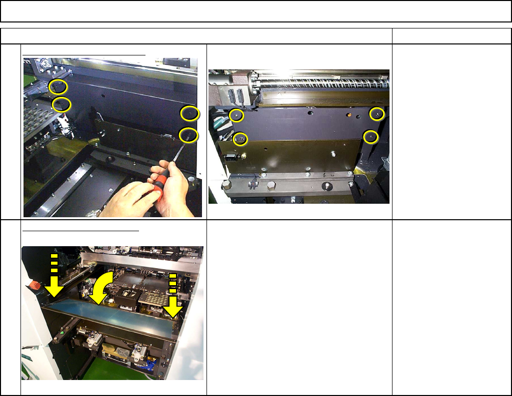
Put back the sensor covers.
Phillips screwdriver #2
Screw M4 8 pcs.
Put back the feeder cover.
Phillips screwdriver #2
Screw M4 2 pcs.
10
9
EJM8A-E-SMA040107-A01-00
Page 4-1-7-4
Maintenance Adjustment Main Body Beam
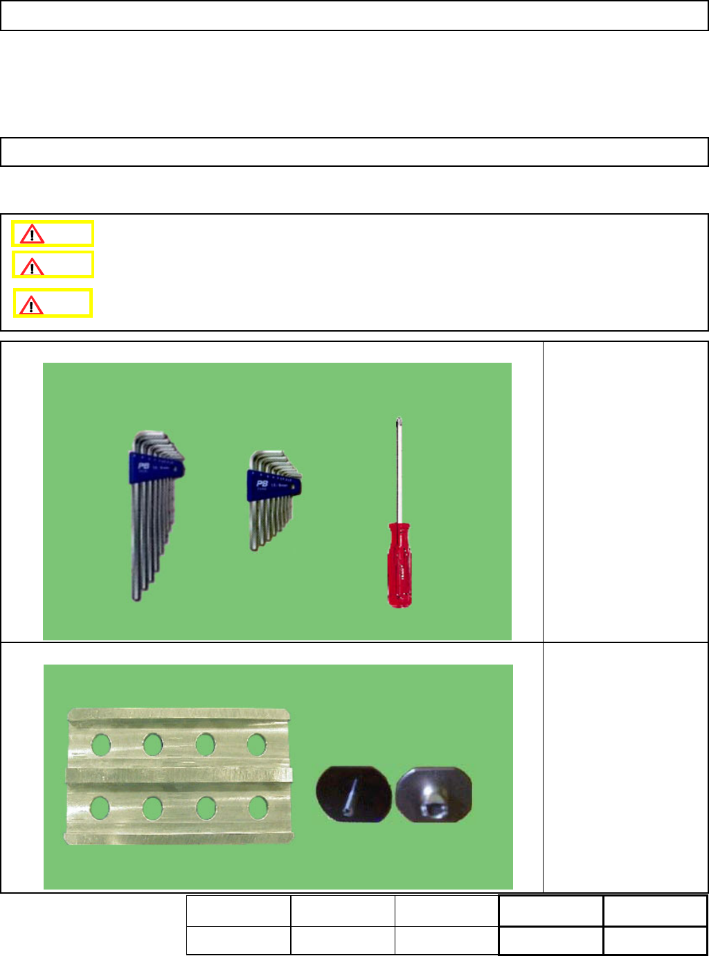
This section describes the procedures for adjusting the angle of the nozzle holders.
・Tools
Phillips screwdriver #2
Allen key 3 mm
Allen key 1.5 mm
・Jig
Nozzle (120 or 130)
8 pcs.
Nozzle Angle Adjusting
Jig
Time taken for adjustment:
15 min.
Part weight: - kgs.
4-1-8 Nozzle Holder Angle Adjustment
Assembly
Adjustment
8min.
Teaching
10min.
Total Time Weight of
Part
Removal
Disassembly
7min.
25min.
kgs
Caution
Dange
r
Warning
EJM8A-E-SMA040108-A01-00
Page 4-1-8-1