CM602all_EJM8AESM_Service Manual.pdf - 第328页
Machinery Part Replacement Main Body Remarks Item Put the side cover back on. Phillips screwdriver #2 Screw M4 4 pcs. Put the feeder cover back on. Phillips screwdriver #2 Screw M4 2 pcs. 13 14 EJM8A-E-SMA050102-A01-00 P…
Machinery Part Replacement Main Body
Remarks
Item
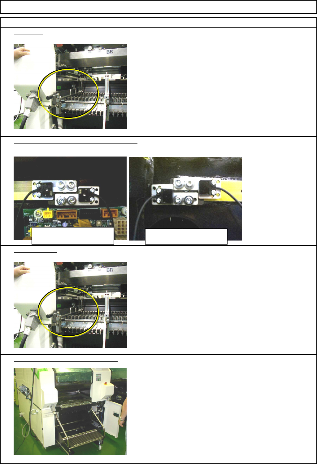
Set the jig.
Precisely position the left and the right
sensors.
Tape Float Sensor
Adjusting Jig
Precisely position the sensor so that the light
axis passes through the hole of the jig. Phillips screwdriver #1
Screw M3 2 pcs.
Remove the jig.
Tape Float Sensor
Adjusting Jig
Remove the feeder gang change cart.
Refer to "Feeder Gang Exchange Cart
Installation and Removal."
Since the feeder covers are left off, block
the light beam of "Tape Float Sensor 1"
with tape or equivalent.
Once the cart is removed, remove the
tape.
Section 5-8-1
Tape
10
11
12
9
Light-sensing sensor
(on left side)
Light-emitting sensor
(on right side)
EJM8A-E-SMA050102-A01-00
Page 5-1-2-4
Machinery Part Replacement Main Body
Remarks
Item
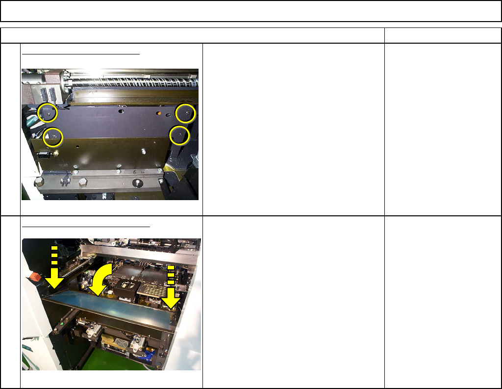
Put the side cover back on.
Phillips screwdriver #2
Screw M4 4 pcs.
Put the feeder cover back on.
Phillips screwdriver #2
Screw M4 2 pcs.
13
14
EJM8A-E-SMA050102-A01-00
Page 5-1-2-5
Machinery Part Replacement Main Body
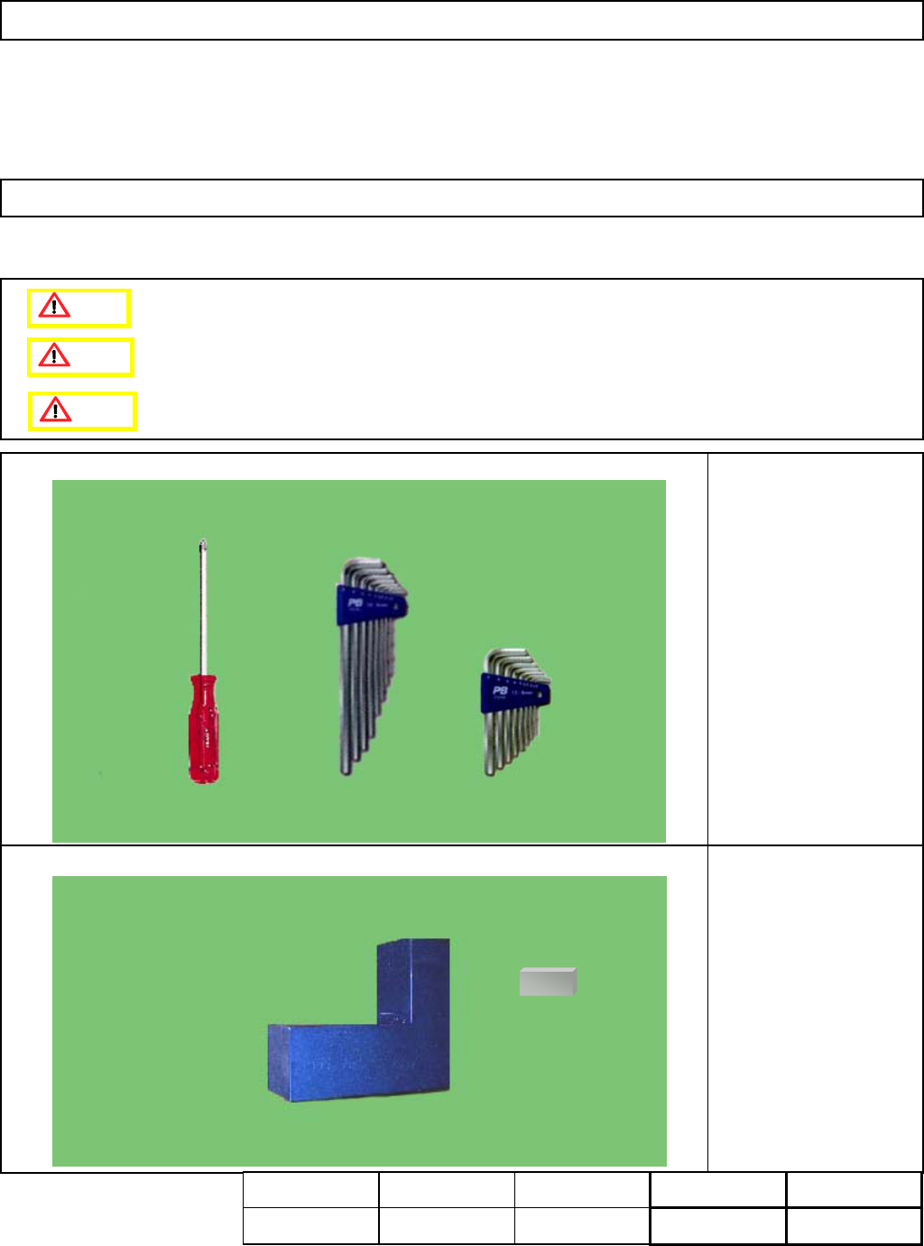
This section describes the procedures for replacing the Y-axis rough sensor.
Tools
Phillips screwdriver #2
Allen key 2.5 mm
Jig
Y-axis Origin Positioning
Jig
Block gauge (2 mm)
5-1-3 Y-axis Rough Sensor Replacement
Assembly
Adjustment
7min.
Teaching
min.
Total Time Weight of
Part
Removal
Disassembly
8min.
15min. kgs
Caution
Dange
r
Warning
EJM8A-E-SMA050103-A01-00
Page 5-1-3-1