CM602all_EJM8AESM_Service Manual.pdf - 第660页
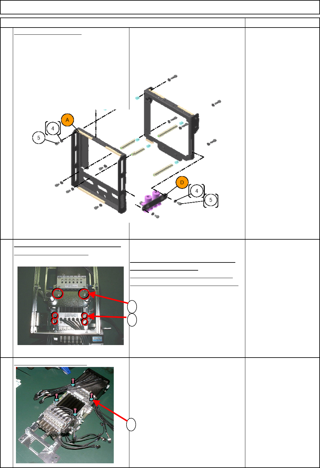
Machinery Part Replacement Remark 12-Nozzle Head Unit Item Remove the front frame. Remove the seven M3 x 6L bolts (5). Remove the front frame. M3 x 6L 7 pcs. Remove the fan bracket and the Z- axis connectin g bracket. 1.…
Machinery Part Replacement
Remark
12-Nozzle Head Unit
Item
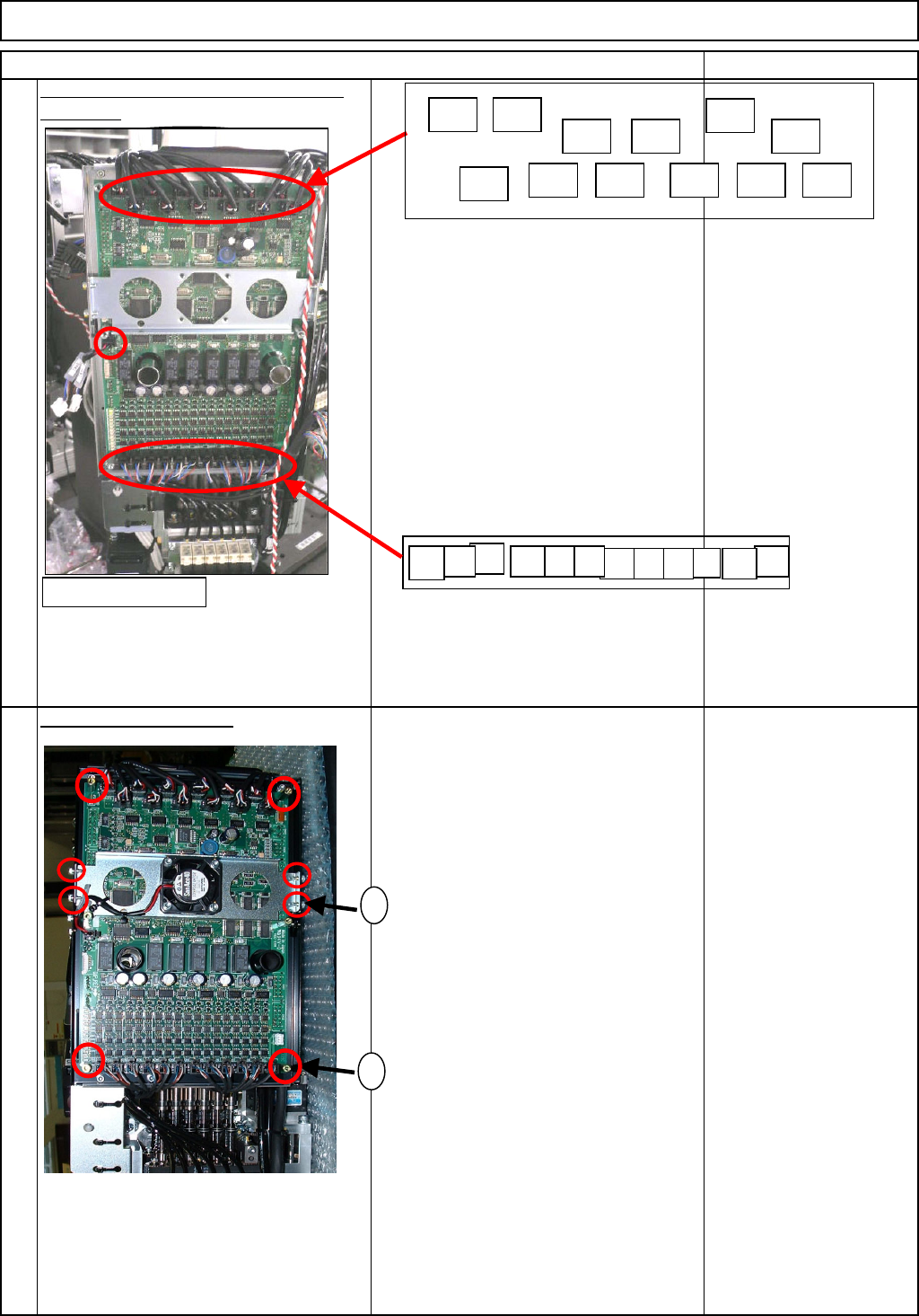
Disconnect the connectors. Cut off the
cable ties.
Remove the front board.
1. Remove the four M3 x 6L bolts (1).
Remove the cooling-fan bracket.
2. Remove the six board-holding bolts (2)
with a wrench.
Remove the board.
M3 x 6L 4 pcs.
Board holding bolt 6 pcs.
8
7
<Front>
1
2
Encoder
NP1
Encoder
NP3
Encoder
NP2
Encoder
NP4
Encoder
NP5
Encoder
NP6
Encoder
NP12
Encoder
NP11
Encoder
NP10
Encoder
NP9
Encoder
NP8
Encoder
NP7
Motor
NP1
Motor
NP2
Motor
NP3
Motor
NP4
Motor
NP5
Motor
NP6
Motor
NP7
Motor
NP8
Motor
NP9
Motor
NP10
Motor
NP11
Motor
NP12
EJM8A-E-SMA051009-A01-00
Page 5-10-9-4
Machinery Part Replacement
Remark
12-Nozzle Head Unit
Item
Remove the front frame.
Remove the seven M3 x 6L bolts (5).
Remove the front frame.
M3 x 6L 7 pcs.
Remove the fan bracket and the Z-
axis connectin
g
bracket.
1. Remove the two M3 x 20L bolts (1).
Remove the fan bracket.
2. Remove the four M3 x 6L bolts (2).
Remove the Z-axis connecting bracket.
M3 x 20L 2 pcs.
M3 x 6L 4 pcs.
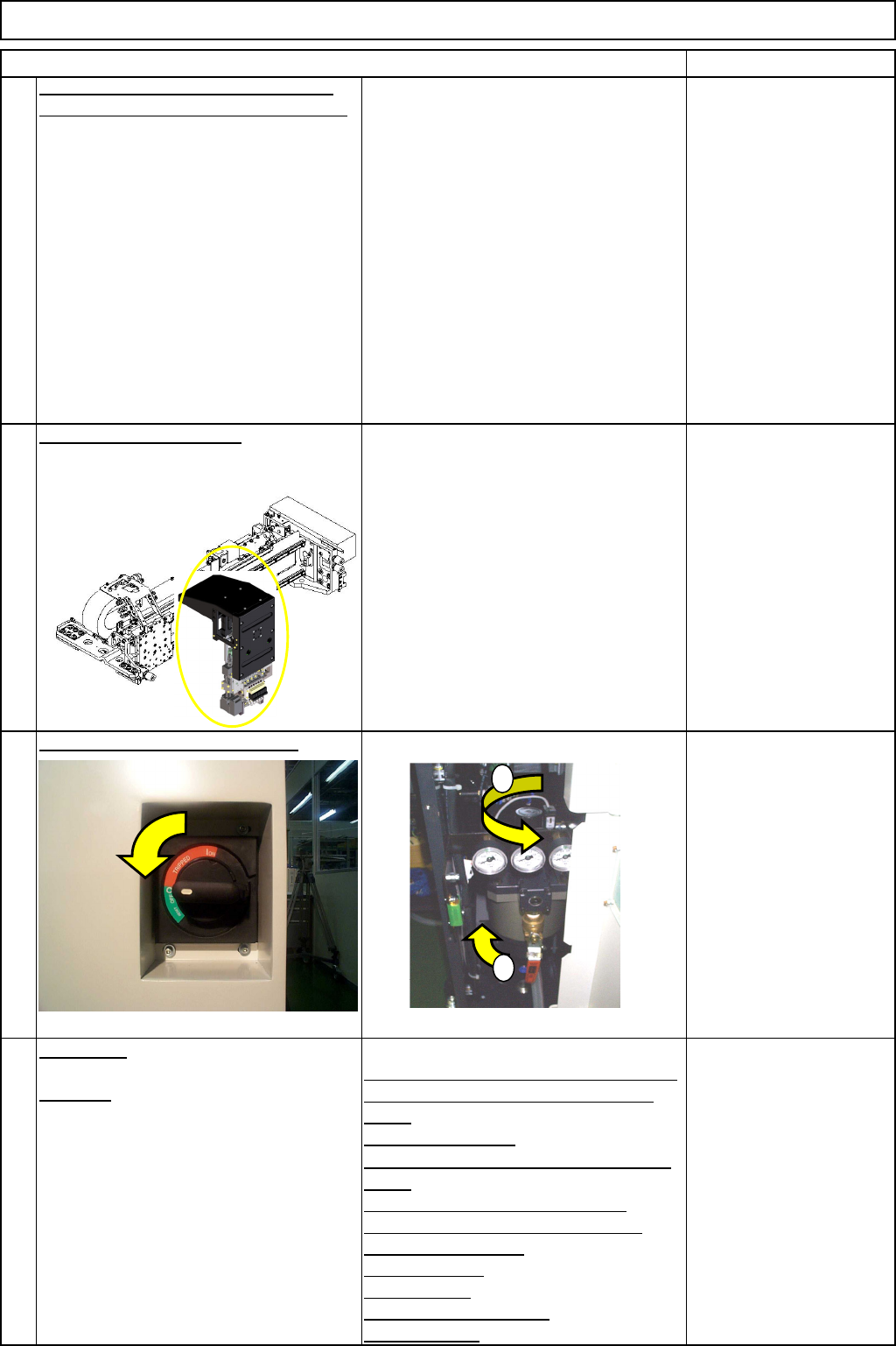
Remove the Z-axis unit.
1. Remove the four M5 x 25L bolts (1).
Remove the Z-axis unit.
* The Z-axis unit cannot be
disassembled. Be sure to replace a
whole unit.
M5x 25L 4 pcs.
9
10
11
1
2
1
EJM8A-E-SMA051009-A01-00
Page 5-10-9-5
Machinery Part Replacement
Remark
12-Nozzle Head Unit
Item
Replace the Z-axis unit. Assemble the
removed parts in reverse order of Steps
2 to 10.
Put the head unit back on.
See "12-Nozzle-Head-Unit
Replacement."
Section 5-10-1
Turn on the power and air suppl
y
.
A
d
j
ustment
Teaching
Head Camera Adjustment (Focus and θ)
Board Recognition Camera XY Origin
Offset
Z-axis Origin Offset
Chip Recognition Camera, θ-axis Origin
Offset
Width Adjusting-axis Origin Offset
Mount Height and Board Positioning
XY Plane Calibration
Pickup Position
Light Intensity
Nozzle Change Position
Mount Position
Section 5-11-1
Section 5-11-2
Section 5-11-3
Section .5-11-4
Section 5-11-5
Section 5-11-6
Section 5-11-7
Section 5-11-8
Section 5-11-9
Section 5-11-10
Section 5-11-11
14
15
12
13
1
2
EJM8A-E-SMA051009-A01-00
Page 5-10-9-6