CM602all_EJM8AESM_Service Manual.pdf - 第669页
Machinery Part Replacement Remarks Item 12-Nozzle Head Teaching Tighten the theta holding set screws. Allen key 1.5 mm Teach "Board Recognition Camera - X and Y-axis Origin Offset." For details, see Sections at…
Machinery Part Replacement
Remarks
Item
12-Nozzle Head Teaching
Remove the
j
i
g
from the conve
y
or.
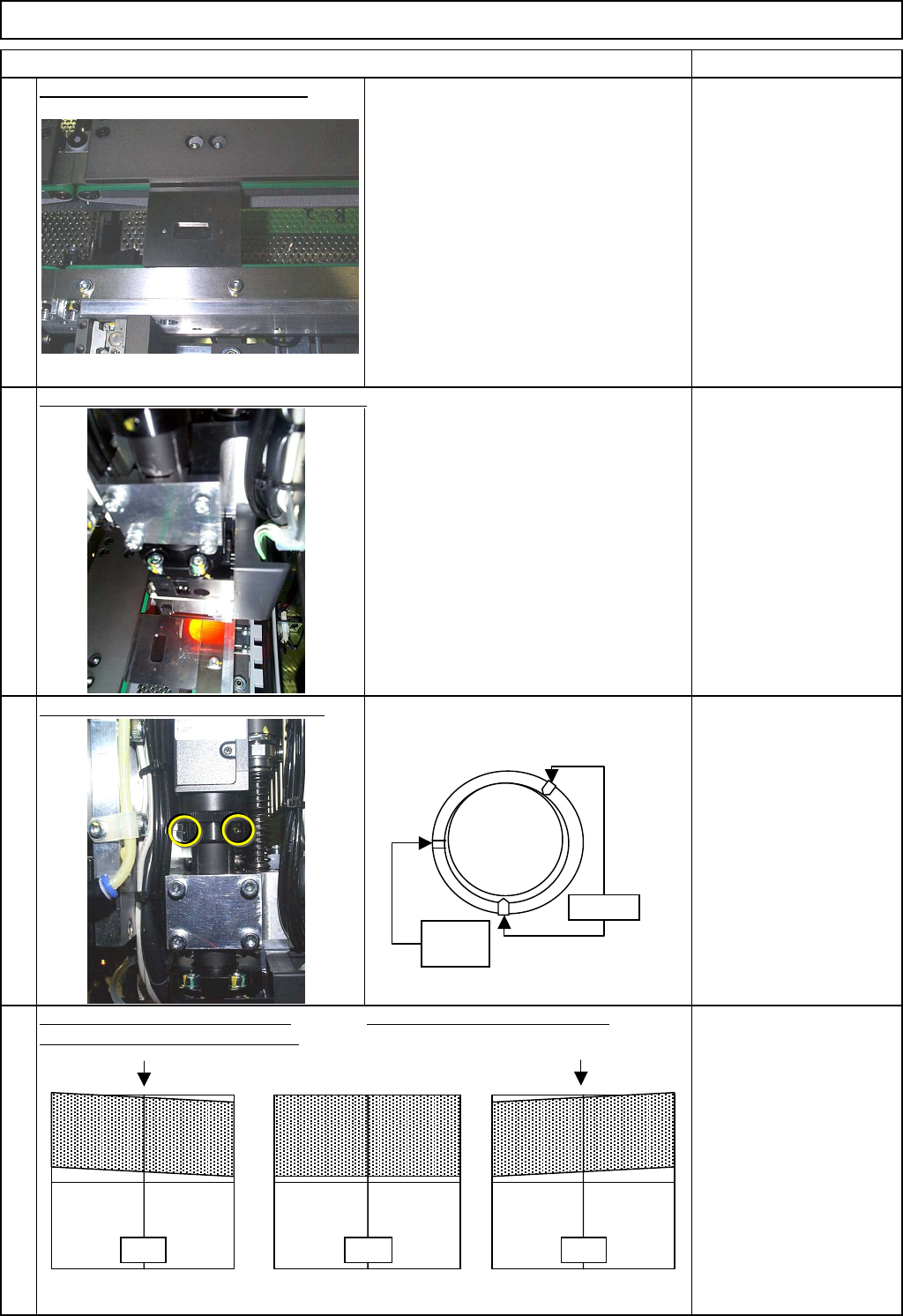
Move the head assembly to the steel rails.
Loosen the theta holding set screws.
Be careful not to let small brass bushings
fall off the screw holes.
Allen key 1.5 mm
Looking at the camera from above, Looking at the camera from above
turn the head camera unit clockwise. turn the head camera unit counterclockwise.
within +/- 0.2°
9
10
11
12
NG OK NG
No
screw
Loosen
EJM8A-E-SMA051101-A01-00
Page 5-11-1-4
Machinery Part Replacement
Remarks
Item
12-Nozzle Head Teaching
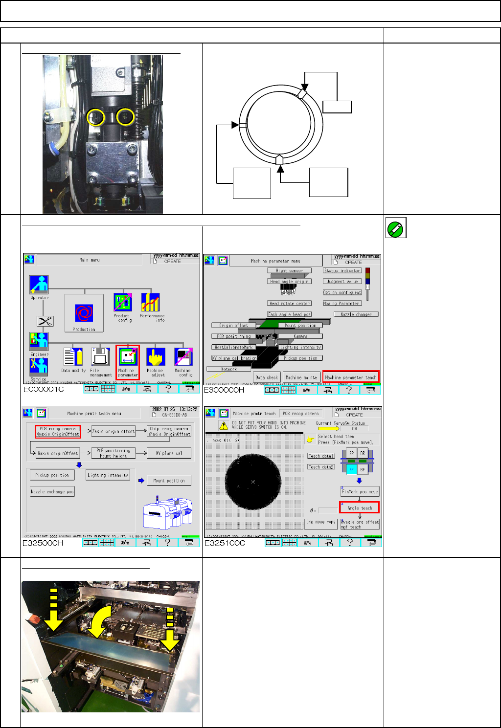
Tighten the theta holding set screws.
Allen key 1.5 mm
Teach "Board Recognition Camera - X and Y-axis Origin Offset."
For details, see Sections at right. Section 5-11-2
Specifications:
within +/- 0.05°
Put the feeder cover back on.
Phillips screwdriver #2
Screw M4 2 pcs.
15
14
13
Lightly
tighten
Lock
No
screw
ON
EJM8A-E-SMA051101-A01-00
Page 5-11-1-5
Machinery Part Replacement
・Tools
None
・Jig
None
12-Nozzle Head Teaching
5-11-2 Board Recognition Camera --- X and Y-axis Origin Offset
Clean the upper surface of the thermal correction pole beforehand.
This section describes the procedures for setting the offset for the origin of the X- and the Y-axes of the board
recognition camera.
Caution
Dange
r
Warning
EJM8A-E-SMA051102-A01-00
Page 5-11-2-1