CM602all_EJM8AESM_Service Manual.pdf - 第265页
Maintenance Adjustment Light Transfer-Head Assembly (3 nozzles) Remarks Item Press [Unlock] and [Jig setting] simultaneously. The head moves to the jig set position (over the NG box). Remove the jig from Head 3. Set the …
Maintenance Adjustment Light Transfer-Head Assembly (3 nozzles)
Remarks
Item
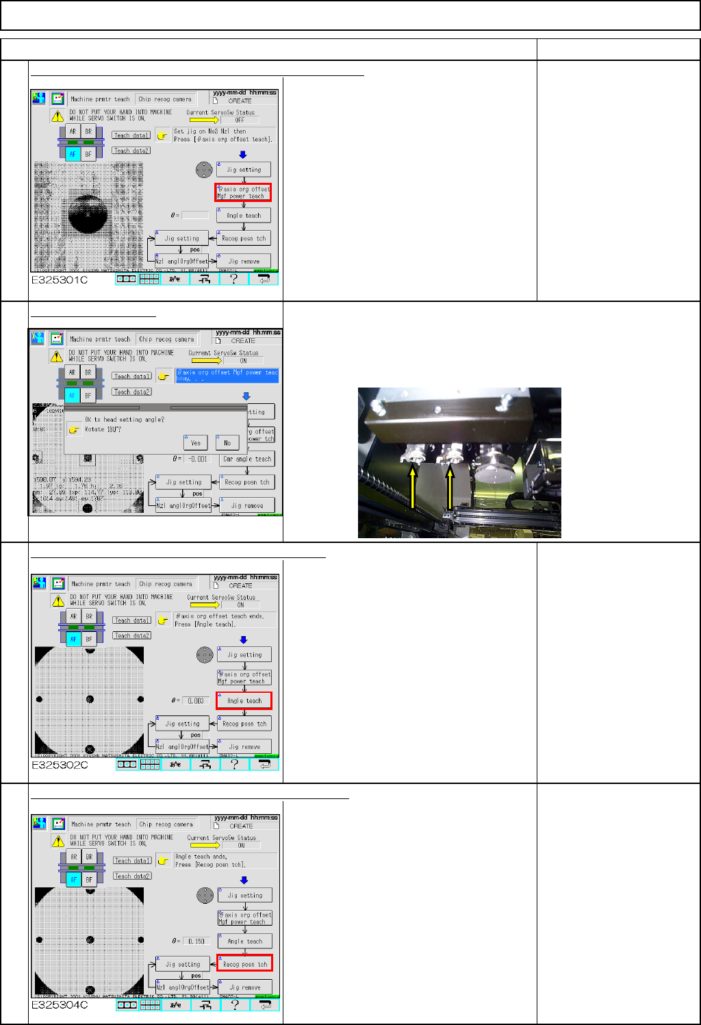
Press [Unlock] and [θaxis org offset Mgf power teach].
The jig is recognized by the chip
recognition camera so that the offsets for
the theta-axis origin and the camera
magnification are entered.
Select "Yes" or "No."
Press [Unlock] and [Angle teach] simultaneously.
After auto recognition, an angle offset is
entered.
Specification:
Theta should be within
+/- 0.05°
If the offset exceeds the
specification, an error will
occur. To avoid an error,
adjust the chip camera.
See Section 4-1-1
"Chip Recognition
Camera Theta Positionig"
Press [Unlock] and [Recog posn tch] simultaneously.
After auto recognition, a recognition
position offset is entered.
If the head theta guide is positioned left,
select "No" so that the jig is recognized immediately.
If the head theta guide is positioned right,
select "Yes" so that the guide rotates 180 degrees and the jig is
recognized.
6
5
8
7
EJM8A-E-SMA040304-A01-00
Page 4-3-4-3
Maintenance Adjustment Light Transfer-Head Assembly (3 nozzles)
Remarks
Item
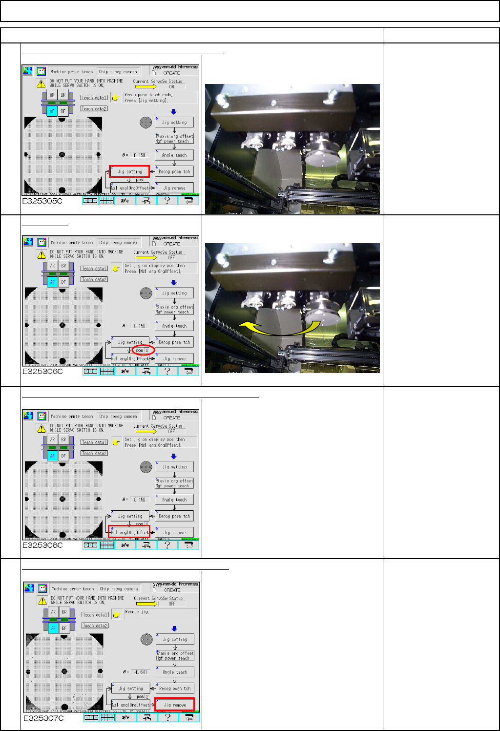
Press [Unlock] and [Jig setting] simultaneously.
The head moves to the jig set position
(over the NG box).
Remove the jig from
Head 3.
Set the jig.
Set the jig on Head 2.
Press [Unlock] and [Nzl anglOrgOffset] simultaneously.
The theta-axis origin offset for each head
is entered.
Teach Heads 1 and 2,
following Steps 7 to 9.
Press [Unlock] and [Jig remove] simultaneously.
The head moves to the jig set position
(over the NG box).
Remove the jig from
Head 2.
10
12
11
9
EJM8A-E-SMA040304-A01-00
Page 4-3-4-4
Maintenance Adjustment Light Transfer-Head Assembly (3 nozzles)
Remarks
Item
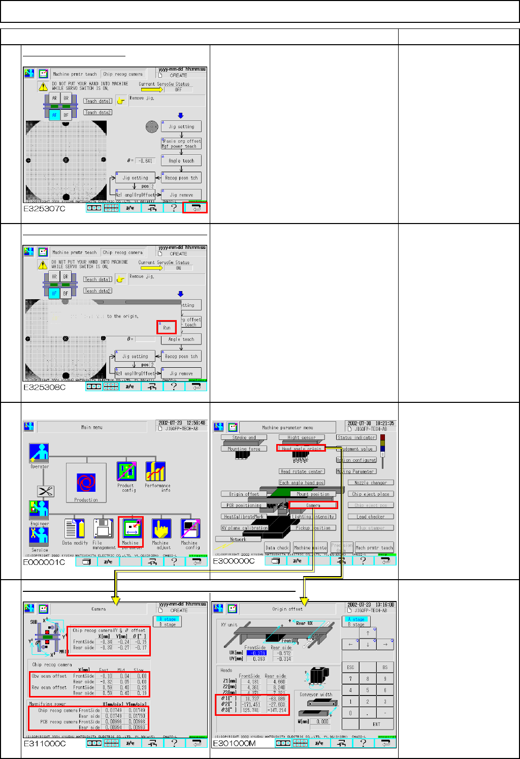
Press the [Return] key.
Press [Unlock] and [Run] simultaneously.
All axes of the selected stage return to
the origin.
The offsets are entered automatically into the screens below:
Offset range:
X, Y&θ offset
(High, Middle & Low speeds)
X :-5.0 to +5.0
Y :-5.0 to +5.0
θ :-0.1 to +1.0
* Reverse scan offset
(High, Middle & Low speeds)
Reverse scan:0.0 to 0.75
* Magnifying power
X Mag. :0.017 to 0.018
Y Mag. :0.017 to 0.018
* Head angle origin
θ: -180 to +180
16
14
15
13
EJM8A-E-SMA040304-A01-00
Page 4-3-4-5