CM602all_EJM8AESM_Service Manual.pdf - 第868页
Remarks Item Option Part and Accessory Replacement PCB-Warp-Sensor Unit Put the feeder cover back on. Allen key 3 mm Screw M4 4 pcs. Turn on the power and air supply. PCB-warp-sensor adjustment Teaching Adjusting the amp…
Remarks
Item
Option Part and Accessory Replacement
PCB-Warp-Sensor Unit
Move the head onto the
j
i
g
.
Height measuring jig
FM-1964
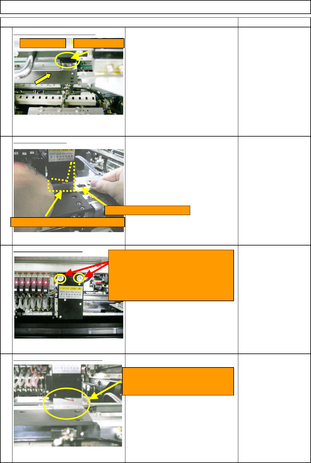
Fit the adjusting jig.
Fit the PCB-warp sensor in the V-shaped
section of the sensor-installing-adjusting
jig FM-1963 shown with the dotted line
at left.
With the sensor making a close contact
with the jig, slide the height-measuring
jig FM-1964 under the jig from the right.
Sensor installing jig
FM-1963
Height measuring jig
FM-1964
Adjust sensor installation.
Wrench M4
M4 x 14L (2 pcs.)
Remove the sensor-installing jig.
22
23
24
25
Move the head. PCB warp sensor
Height measuring jig FM-1964
Sensor-installation-adjusting jig FM-1963
Remove the installation-adjusting jig
FM-1963 and the height-measuring
j
ig FM-1964.
Loosen the two M4x14L bolts. Fit the
sensor in the V-shaped section of the
sensor-installation-adjusting jig FM-1963.
With the sensor making a close contact
with the jig, tighten the two M4 x 14L
bolts.
EJM8A-E-SMA060504-A01-00
Page 6-5-4-8
Remarks
Item
Option Part and Accessory Replacement
PCB-Warp-Sensor Unit
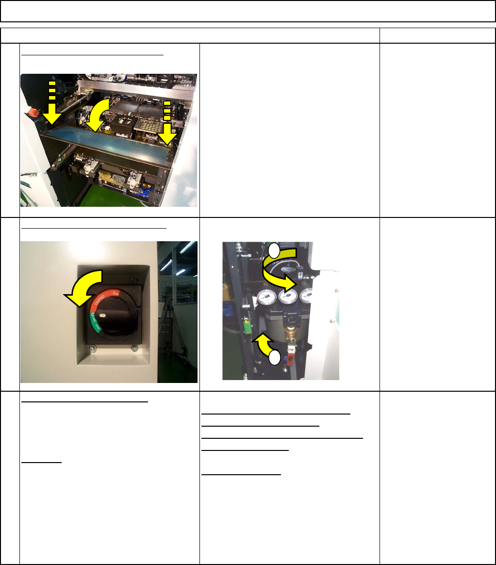
Put the feeder cover back on.
Allen key 3 mm
Screw M4 4 pcs.
Turn on the power and air supply.
PCB-warp-sensor adjustment
Teaching
Adjusting the amplifier 0 reference
position (0-volt adjustment)
Adjusting the slant (span) of amplifier
(+2-volt adjustment)
XY offset teaching
See Section 6-5-5
27
26
28
1
2
EJM8A-E-SMA060504-A01-00
Page 6-5-4-9
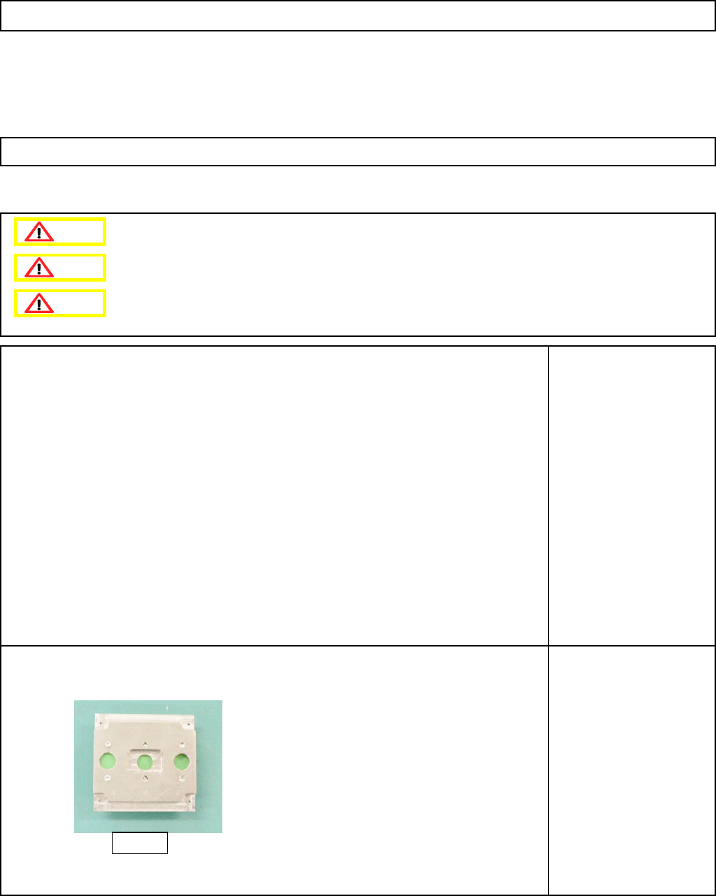
This section describes the procedures for teaching the height-measuring sensor (High-speed head).
• Tools
• Jigs
Height measuring jig
FM-1964
PCB-Warp-Sensor Unit
6-5-5 Height Measuring Sensor Teaching (High-speed head)
Option Part and Accessory Replacement
Dange
r
Warning
Caution
FM-1964
EJM8A-E-SMA060505-A01-00
Page 6-5-5-1