CM602all_EJM8AESM_Service Manual.pdf - 第358页
Remove the secondary parts from the desired stage, referring to "Y-axis Secondary-Part Replacement." 3 4 Remarks Main Body Machine Part Replacement Wrench 3 mm Screw M4 (Special) x 2 1 Item Turn off the power a…
I Since this adjustment requires releasing the safety cover switch, only those who are
authorized to release it based on the Document "Key Switch/Key Disk Receipt
Confirmation and Safety Precautions" are permitted to perform this adjustment.
Removal/Disassembly
Teaching
Assembly/Adjustment
• This section describes the procedures for replacing the Y-axis primary-part.
Total Time Part Weight
Y-axis primary-part sliding
stand
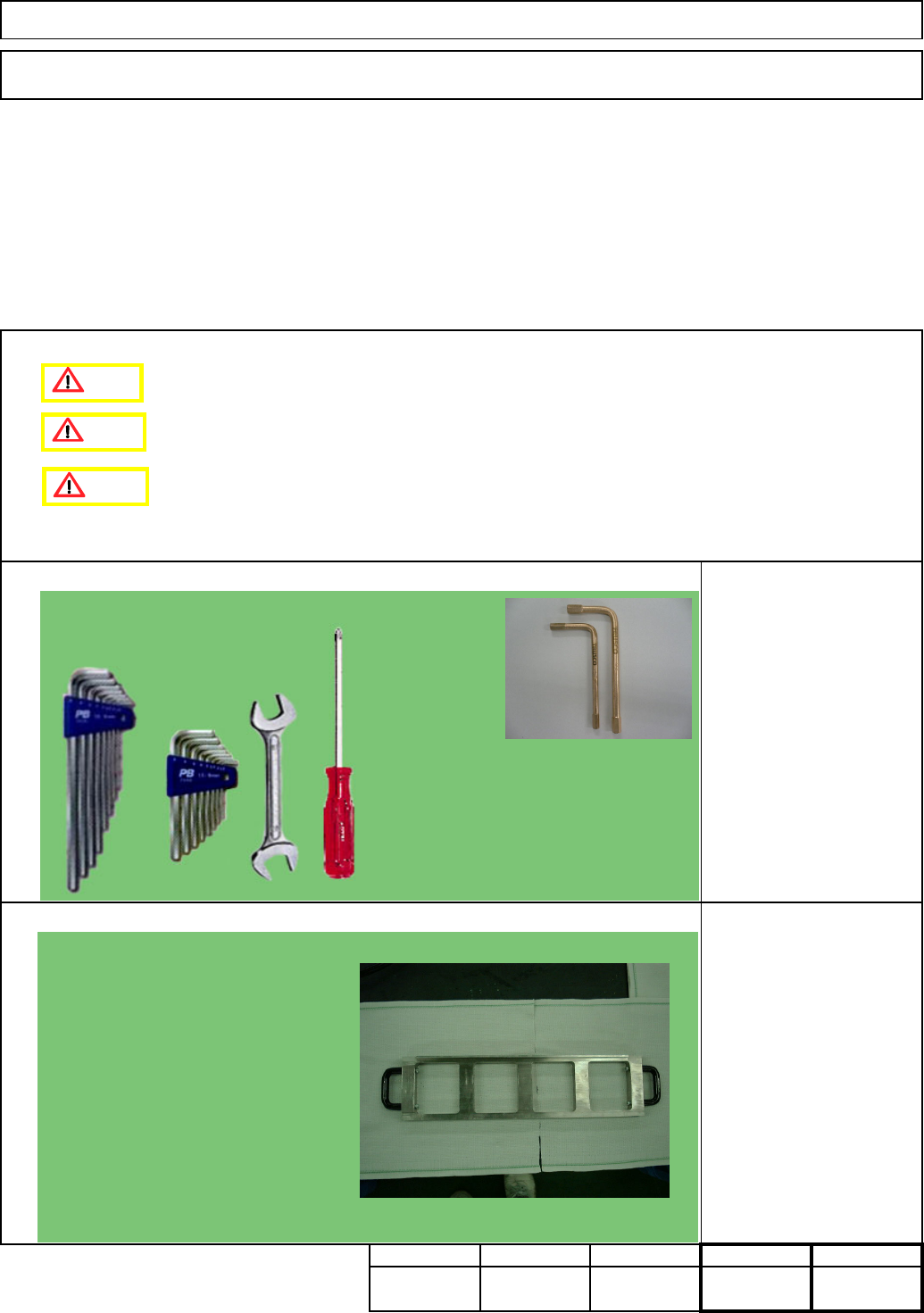
Tools
Jig
Phillips screwdriver #2
Allen keys 3 - 5mm
Wrench 14 and 19 mm
Non-magnetic Allen key
180
Min.
kg
90Min.90 Min.Min.
Main Body
5-1-8 Y-axis Primary-Part Replacement
Machinery Part Replacement
Caution
Danger
Warning
Non-magnetic Allen key (Straight)
Should be short-processed.)
Picture: Manufacturer: TRUSCO
NAKAYAMA
Flame-proof tool series
Model: BHX-4, BHX-5 (Size M4 and M5)
EJM8A-E-SMA050108-A01-00
Page 5-1-8-1
Remove the secondary parts from the desired stage, referring to "Y-axis
Secondary-Part Replacement."
3
4
Remarks
Main BodyMachine Part Replacement
Wrench 3 mm
Screw M4 (Special) x 2
1
Item
Turn off the power and the air.
Remove the side covers.
Remove the feeder cover.
2
1
2
AF
BR
AR
BF
1
2
Stage A
Stage B
Operator's side
Ex. Remove the four secondary-parts from the AF as shown above.
Center frame
EJM8A-E-SMA050108-A01-00
Page 5-1-8-2
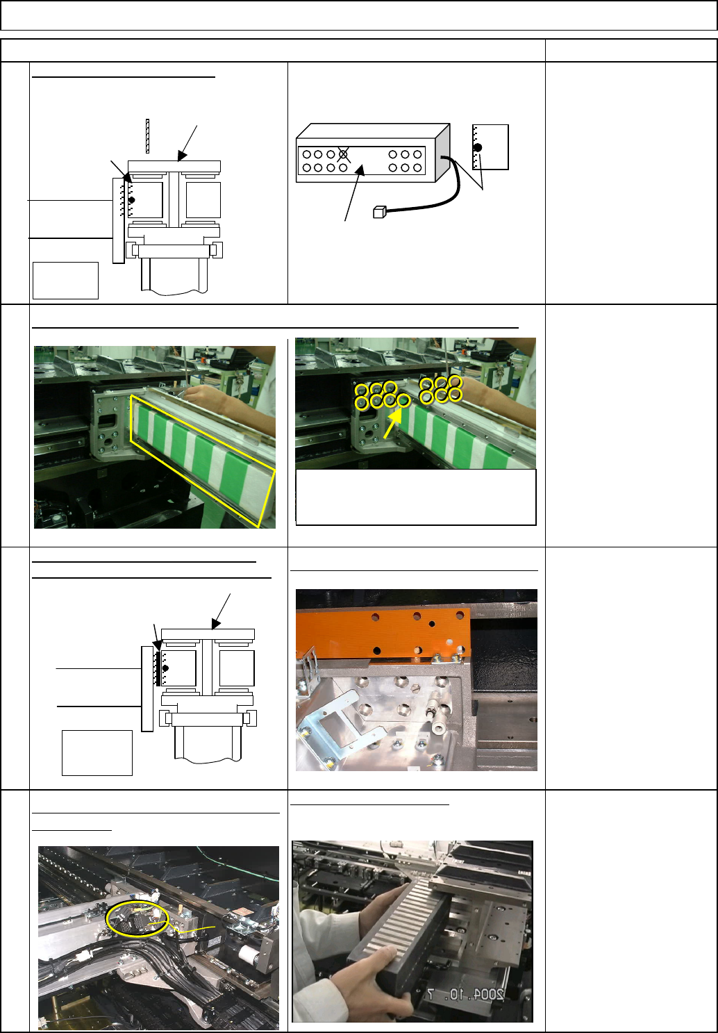
Be careful of magnetism when working on the parts.
8
7
Item
5
Put a cover over the X-axis secondary parts to avoid letting a tool be attracted.
6
Remarks
Use a non-magnetic Allen
key (M5).
Main Body
Move the beam towards you.
Machine Part Replacement
Remove the brown plate from the space
between the secondary part and the beam.
Picture after the brown plate is removed
Remove the primary-part connector and
the cable tie.
Remove the primary part.
Center frame
Stage
A
When seen from operator
Primary part
Beam
(
Mountin
g
p
osition
)
Cable
(Diagonally shaded
area: Mount position)
Side of primary part
Front of primary part
Although there are14 primary-part
holding bolts, one hole is not used. (X
mark)
The primary part is heavy; hold it with
your hand when loosening the bolts
so as not to let it drop.
Center frame
Stage A
When seen from operator
Brown plate
Beam
Brown plate
EJM8A-E-SMA050108-A01-00
Page 5-1-8-3