CM602all_EJM8AESM_Service Manual.pdf - 第836页
Remark Component-Thickness-Measuring Unit Item Option Part and Accessory Replacement FM-1962(1) (1. Component-height- detection-sensor- adjusting-power box) Loosen the M4 bolts (1). Moving the light- emitting-axis horizo…
Remark
Component-Thickness-Measuring Unit
Item
Option Part and Accessory Replacement
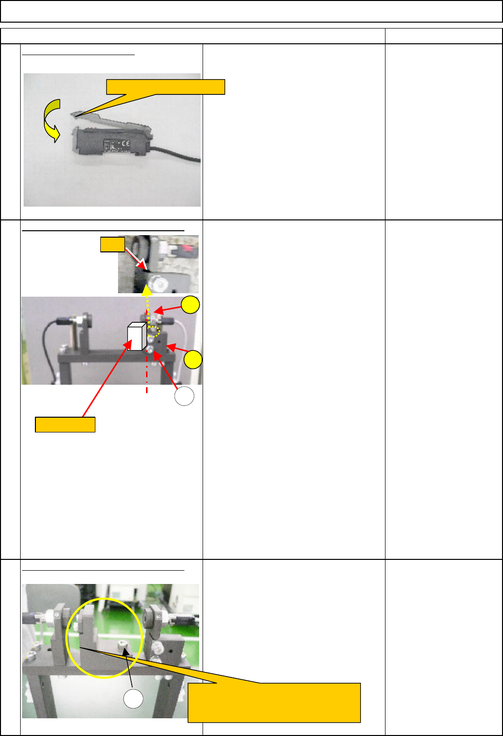
Close the amplifier cover.
15
Light-axis adjustment (Preparation 1)
1. Adjust the gap between the block A
and the plate B,using the adjusting bolts
(1) until the gap becomes 0.
2. Keeping the gap 0, press the block
gauge (10 mm) against the reference
surfaces of the block A and the block B.
Level the block A and the plate B by
aligning them with the block gauge. Fix
them by tightening the adjusting bolts
(1).
<Caution>
Basically it is not necessary to position
the light-sensing plate.
(1) M4 x 16L (2 pcs.)
A: Block
B: Plate
Block gauge (10 mm)
Light-axis adjustment (Preparation 2)
Fix the (2. component-thickness-
measuring-unit-light-axis-adjusting jig) in
place with the bolt (1).
(1) M4 x 16L
FM-1962(2)
(2. Component-thickness-
measuring-unit-light-axis-
adjusting jig)
16
17
A
1
FM-1962(2)
Component-thickness-measuring-unit-
light-axis-adjusting jig
Close the amplifier cover.
1
B
Block gauge
Gap
EJM8A-E-SMA060405-A01-00
Page 6-4-5-6
Remark
Component-Thickness-Measuring Unit
Item
Option Part and Accessory Replacement
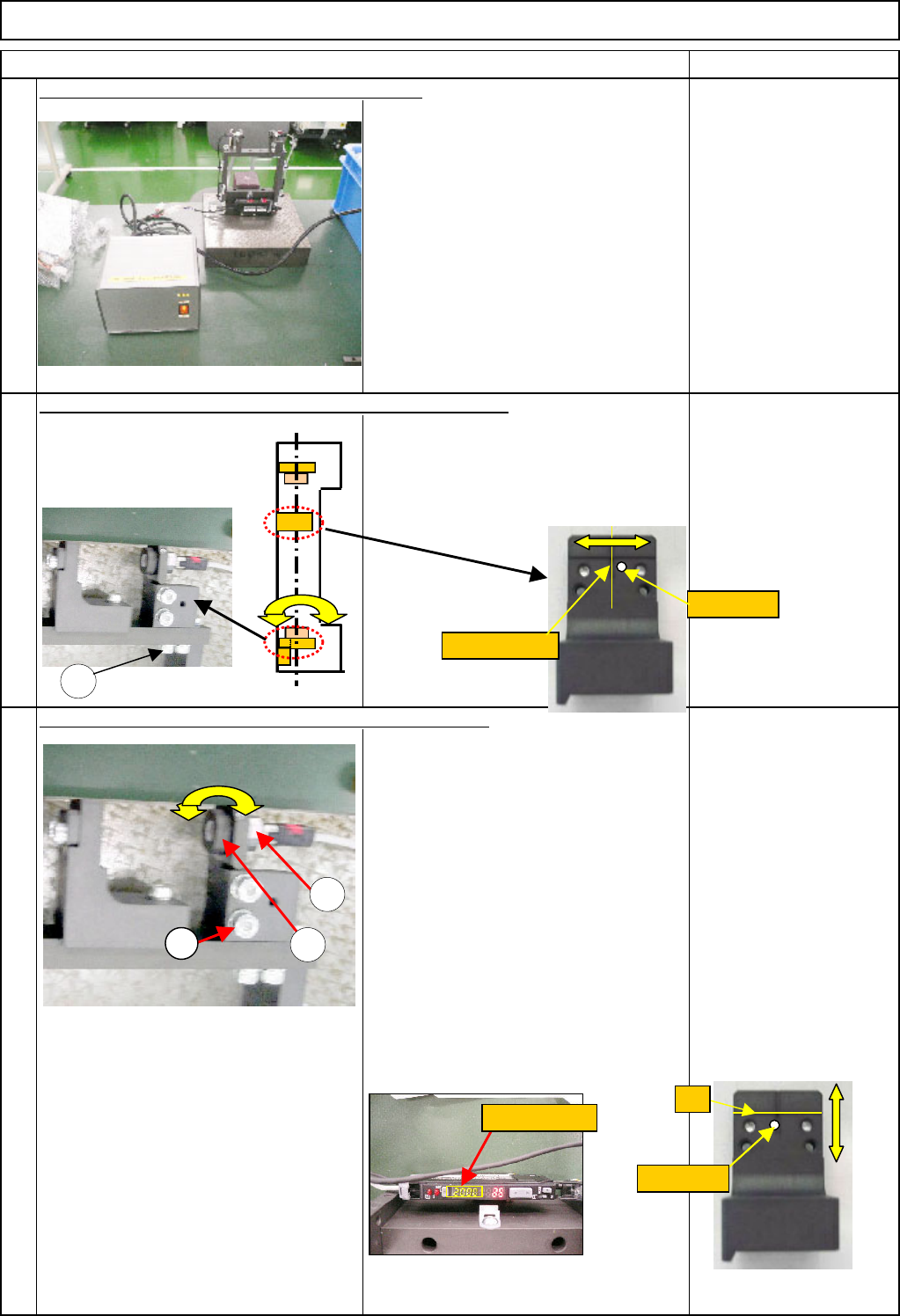
FM-1962(1)
(1. Component-height-
detection-sensor-
adjusting-power box)
Loosen the M4 bolts (1). Moving the light-
emitting-axis horizontally, align the laser light
with the center of the horizontal slit of the
FM-1962 (2) (2. component-thickness-
measuring-unit-light-axis-adjusting jig).
Tighten the M4 bolts (1).
Bolt M4
M4 x 16L (2 pcs.)
FM-1962(2)
(2. component-thickness-
measuring-unit-light-axis-
adjusting jig)
Loosen the M6 nut (1). Turn the light-
emitting-axis eccentric pin to align the
laser light with the center of the vertical
slit of the FM-1962 (2) (2. Component-
thickness-measuring-unit-optical-axis-
adjusting jig). Find a position at which
the amplifier value (light-sensing
amount) is 2000 or more. Tighten the
M6 nut.
If the laser light is positioned far from
the vertical slit in the vertical direction,
loosen the bolt (3) and align the light-
axis with the groove.
Nut M6
FM-1962(2)
(2. component-thickness-
measuring-unit-optical-
axis-adjusting jig)
18
19
20
Connect the power box (24VDC) to the amplifier.
Adjust the light-emitting light-axis in the horizontal direction.
Adjust the light-emitting light-axis in the vertical direction.
Laser light
1
Horizontal slit
1
2
3
2000 or more
Slit
Laser light
EJM8A-E-SMA060405-A01-00
Page 6-4-5-7
Remark
Component-Thickness-Measuring Unit
Item
Option Part and Accessory Replacement
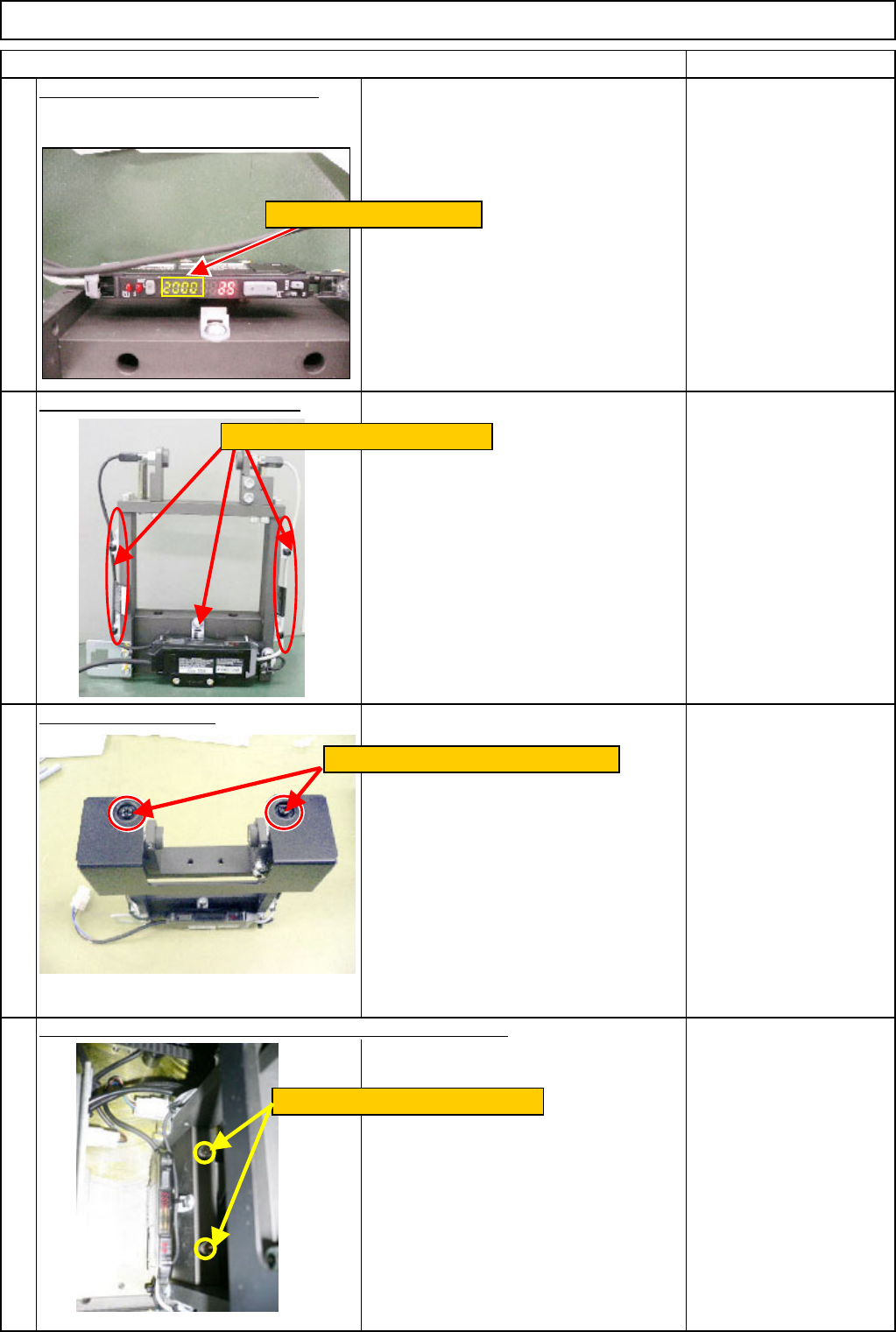
When the amplifier value is 2000 or
* If the amplifier value does not exceed
2000 in Steps 20 and 21, adjust the
light-sensing-light-axis in the horizontal
direction.
Adjustment method:
See Step 19.
Secure the cables with cable ties.
Nipper
Put the cover back on.
Phillips screwdriver
Allen key M6
M6 x 60L (2 pcs.)
24
21
22
23
Install the component-thickness-sensor unit on the machine.
Install the cover with two M4 screws.
Tighten the two M6 x 60L screws.
In the case of 2000 or less
Secure the cables with cable ties.
EJM8A-E-SMA060405-A01-00
Page 6-4-5-8