CM602all_EJM8AESM_Service Manual.pdf - 第532页
Remarks 9 Apply grease to the loose bushings. Put the linear guides into the linear rails Tools and Specifications with their capillary plates up. Machinery Part Replacement Z Unit (3-nozzle type) 10 Put the Z plate back…
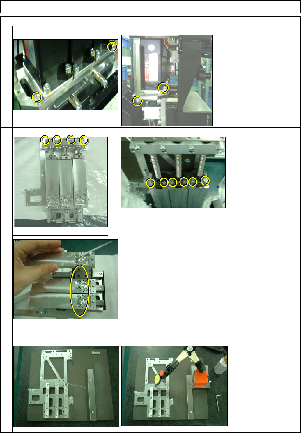
Machinery Part Replacement
Z Unit (3-nozzle type)
Tools and Specifications
Remove the ball screws.
Tools and Specifications
Allen key 2.5 mm
Screw M4x12L 4 pcs.
6
5
Item
Remove a set of three Z-motors.
Allen key 2.5 mm
Screw M3x16L 6 pcs.
M3x30L 4 pcs.
Tools and Specifications
Remarks
Allen key 3 mm
Screw M4x8L 12 pcs.
7
Remove the head unit holding plate.
Allen key 2.5 mm
Straightedge
Magnetic stand
Dial gauge
Screw M3x8L 6 pcs.
Squareness: 0.01 mm or
less
Tools and Specifications
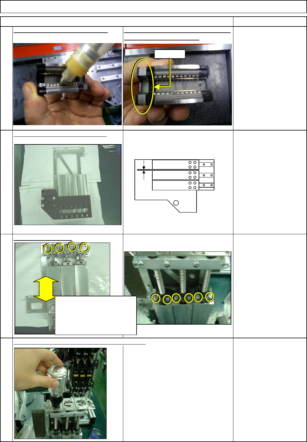
8
Replace the linear rail. Adjust it to parallel with the base plate.
EJM8A-E-SMA050507-A01-00
Page 5-5-7-3
Remarks
9
Apply grease to the loose bushings.
Put the linear guides into the linear rails
Tools and Specifications
with their capillary plates up.
Machinery Part Replacement
Z Unit (3-nozzle type)
10
Put the Z plate back on with the jig.
Tools and Specifications
Allen key 3 mm
Feeler gauge
Screw M4x8L 12 pcs.
Gap between the heads:
A: 0.5 mm
Item
11
Install the ball screws.
Tools and Specifications
Allen key 2.5 mm
Screw M3x16L 6 pcs.
M3x30L 4 pcs.
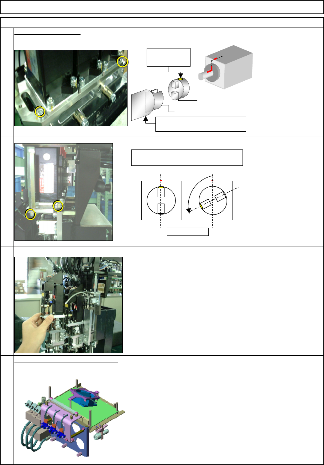
12
Tools and Specifications
Allen key 2.5 mm
Screw M3x16L 6 pcs.
Specifications:
T: 250cN・m or less
Lock the ball screws, checking the rotation torque.
Upward
A
Moving up and down the
linear guides, find a point at
which the guides slid
e
smoothly. Then lightly tighten
the screws
EJM8A-E-SMA050507-A01-00
Page 5-5-7-4
Refer to "Head Unit Replacement."
Machinery Part Replacement
Z Unit (3-nozzle type)
Item Remarks
13
Install the Z-axis motor.
Tools and Specifications
Allen key 2.5 mm
Screw M3 2 pcs.
14
Tools and Specifications
15
Put the head unit back on.
Tools and Specifications
Section 5-4-2
Allen key 2.5 mm
Screw M3x8L 4 pcs.
16
Put the upper board bracket back on.
Tools and Specifications
Allen key 3 mm
Allen key 4 mm
Screw M4x8L 1 pc.
M5x12L 3 pcs.
Screw-hole
position
D
E
Raise the linear guide to
maximum.
Top view
The screw hole of "D" should be positioned
more than 90 degrees away from the
k
EJM8A-E-SMA050507-A01-00
Page 5-5-7-5