CM602all_EJM8AESM_Service Manual.pdf - 第844页
Remarks PCB-Warp-Sensor Unit Item Option Part and Accessory Replacement Turn on the power and air supply. PCB-warp-sensor adjustment Teaching Adjusting the amplifier 0 reference position (0-volt adjustment) Adjusting the…
Remarks
PCB-Warp-Sensor Unit
Item
Option Part and Accessory Replacement
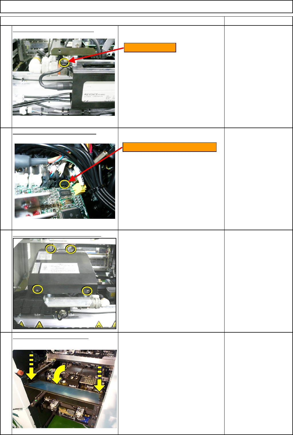
Secure the amplifier cable. - (2)
Connect the amplifier connector.
* Amplifier connector CN13
Put the head upper cover back on.
Phillips screwdriver #2
Truss M4 screw 4 pcs.
Put the feeder cover back on.
Allen key 3 mm
Screw M4 4 pcs.
16
13
14
15
Connect the amplifier connector.
Cable-tie position
EJM8A-E-SMA060501-A01-01
Page 6-5-1-5
Remarks
PCB-Warp-Sensor Unit
Item
Option Part and Accessory Replacement
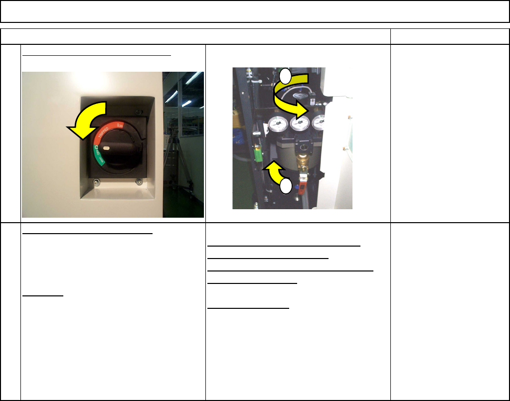
Turn on the power and air supply.
PCB-warp-sensor adjustment
Teaching
Adjusting the amplifier 0 reference
position (0-volt adjustment)
Adjusting the slant (span) of amplifier
(+2-volt adjustment)
XY offset teaching
See Section 6-5-5
17
18
1
2
EJM8A-E-SMA060501-A01-01
Page 6-5-1-6
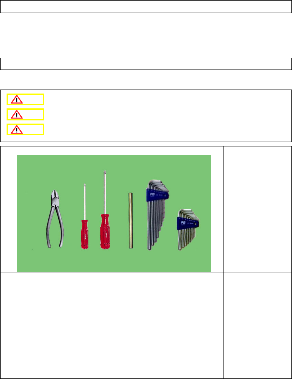
This section describes the procedures for replacing the PCB-warp-sensor amplifier (12-nozzle head spec.)
• Tools
Phillips screwdriver #1
Phillips screwdriver #2
Allen key 5 mm
Pipe
Nipper
Option Part and Accessory Replacement
PCB-Warp-Sensor Unit
6-5-2 PCB-Warp-Sensor-Amplifier Replacement (12-Nozzle-Head Spec.)
• Jigs
Dange
r
Warning
Caution
EJM8A-E-SMA060502-A01-01
Page 6-5-2-1