CM602all_EJM8AESM_Service Manual.pdf - 第1053页
the bolt shown with the arrow below. 3 4 Rea r 2 Direct Tray Remark Allen key 2 mm Phillips screwdriver #1 M3 6 pcs. Truss 6 pcs. Phillips screwdriver #2 Screw M4 4 to 6 pcs. Phillips screwdriver #2 Screw M4 11 pcs. Open…
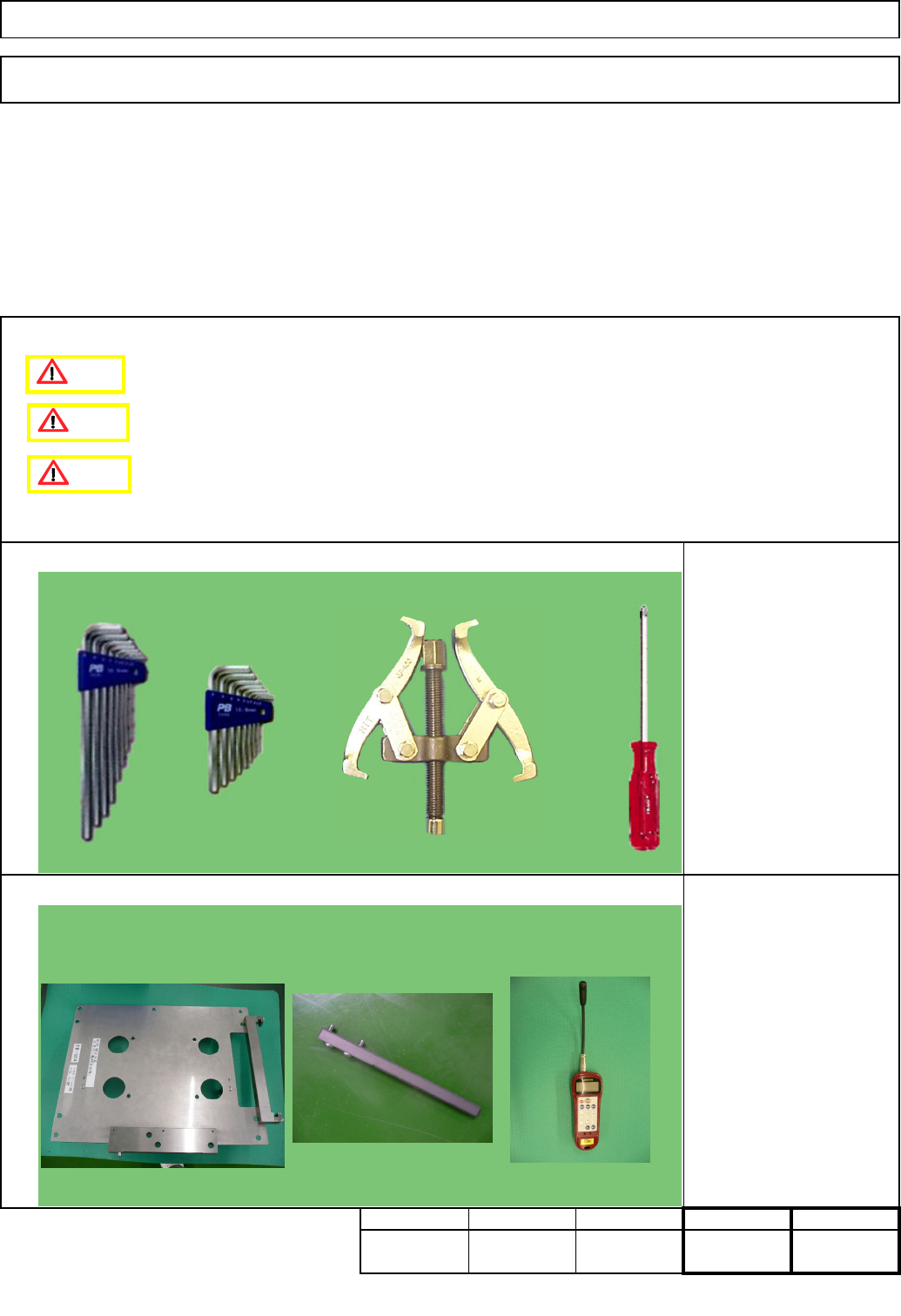
Jig: FM-1924
Pulley-holding jig
Tension gauge
Phillip screwdriver #2
Allen key 2 mm
Allen key 3 mm
Allen key 4 mm
Pulley remover
Tension gauge
Torque wrench
Teaching
Direct Tray
• This section describes the procedures for replacing the extension-axis motor.
7-2-10 Extension-axis Motor Replacement
Min.
30
Removal/Disassembly
20
Min.
kgs.
80
Part Weight
Assembly/Adjustment
Min.
Total
Min.
30
Tray
Tool
Jig
Caution
Danger
Warning
EJM8A-E-SMA070210-A01-00
Page 7-2-10-1
the bolt shown with the arrow below.
3
4
Rea
r
2
Direct Tray
Remark
Allen key 2 mm
Phillips screwdriver #1
M3 6 pcs.
Truss 6 pcs.
Phillips screwdriver #2
Screw M4 4 to 6 pcs.
Phillips screwdriver #2
Screw M4 11 pcs.
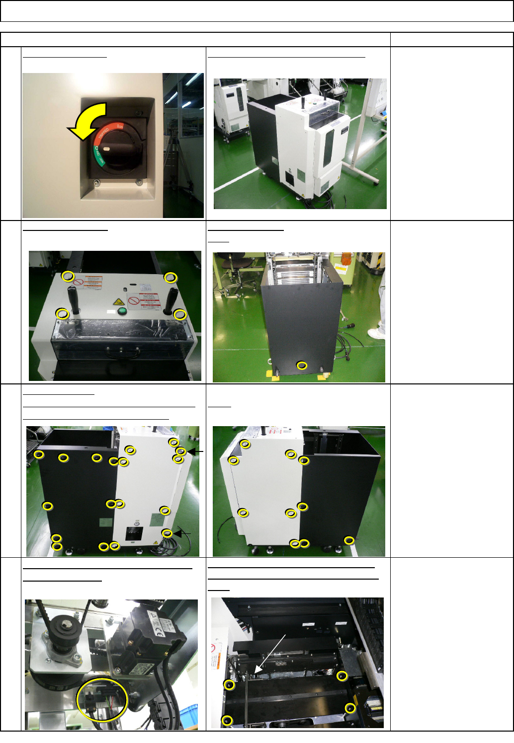
Open the cover.
RightLeft. Stay at the front side when removing
Turn off the power.
Remove the bolt.
Remove the tray from the machine.
Item
Tray
Remove the motor connectors ENTP2
(4) and TPM2 (4).
1
Remove the four Hexagon bolts, and then
the palette table. Be careful not to drop the
bolts.
Remove the cover.
TP-
axis
EJM8A-E-SMA070210-A01-00
Page 7-2-10-2
6
7
8
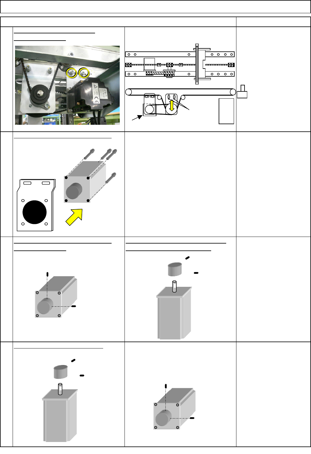
Aligning one screw with the D-shaped
cut of the motor shaft, tighten it.
Remove the motor from the bracket.
5
Remove the motor.
Direct Tray
Item
Tray
Allen key 2 mm
Setscrew M3 2 pcs.
Replace the motor. Fit the pulley.
Remove the motor pulley setscrews.
Remove the pulley.
Remark
Allen key 2 mm
Setscrew M3 2 pcs.
Pulley remover
Allen key 4 mm
Screw M5 4 pcs.
Loosen the motor belt tension.
Allen key 4 mm
Screw M5 2 pcs.
Extension-axis motor
Supply
section
A
EJM8A-E-SMA070210-A01-00
Page 7-2-10-3