CM602all_EJM8AESM_Service Manual.pdf - 第899页
Shuttle Tray Tray 17 Put the side cover back on. Phillips screwdriver #2 M4 x 8L Truss 8 pcs. Item Remarks EJM8A-E-SMA070103-A01-00 Page 7-1-3-6
14
Item
Tray Shuttle Tray
15
Once the adjustment is complete,
Specifications:
T≦0.05㎜
Feeler gauge
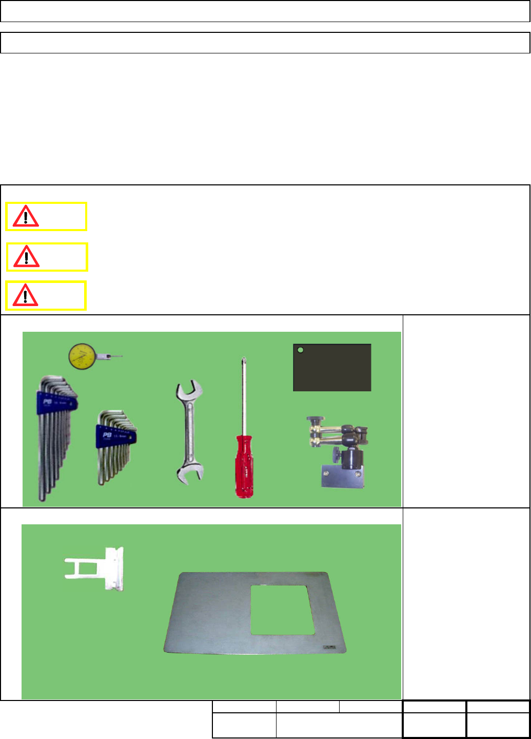
Jig: FM-1188
Check the gap from the guide to
check the gap of door guide. the jig when closing the door.
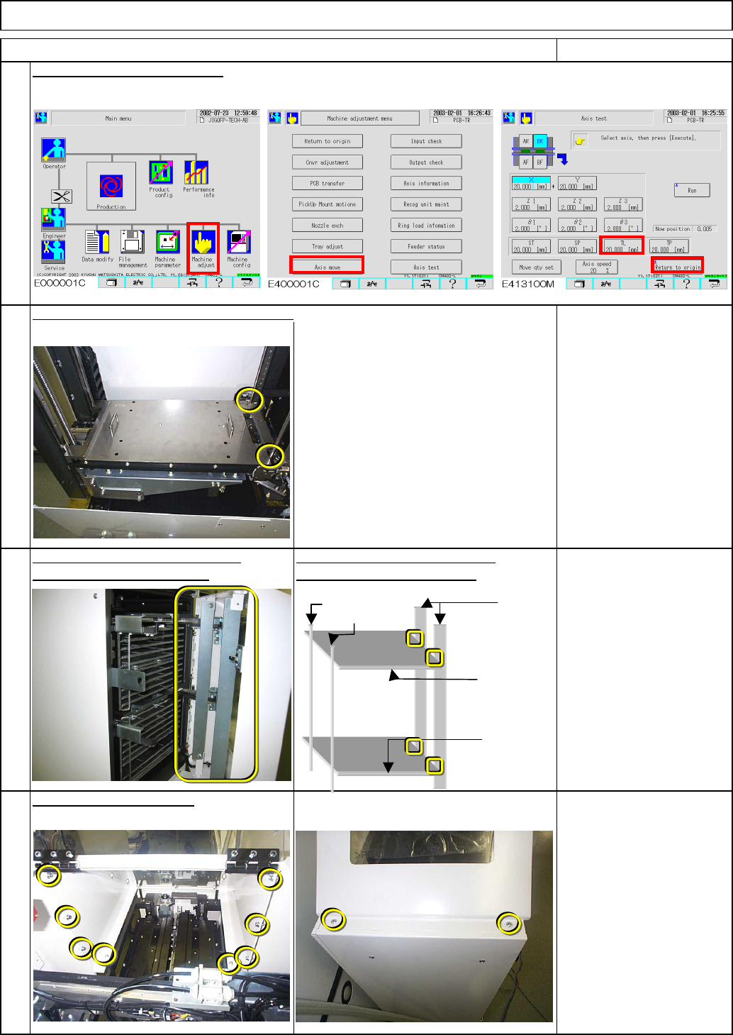
16
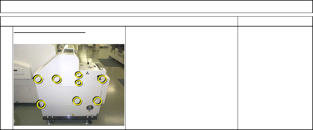
Put the top cover back on.
Allen key 3 mm
Philips screwdriver #2
M4 x 8L 8 pcs.
M4 x 10L Truss 2 pcs.
Confirm the position of the lower stoppers.
Remarks
13
Return the lift-axis to the origin.
Door
guide
NG palette
position
Lower
position
of Lower
magazine
Magazine
shutter
EJM8A-E-SMA070103-A01-00
Page 7-1-3-5
Shuttle TrayTray
17
Put the side cover back on.
Phillips screwdriver #2
M4 x 8L Truss 8 pcs.
Item Remarks
EJM8A-E-SMA070103-A01-00
Page 7-1-3-6
15
Min. Min.
Shuttle TrayTray
・This section describes the procedurures for adjsuting the lift-axis storke.
Key switch
FM-0558: Palate jig
7-1-4 Lift-axis Stroke Adjustment
Phillips screwdriver #2
Allen key 3 to 5 mm
Wrench 14 mm
Magnetic stand
Magnetic stand holding iron
plate
Dial gauge
kgs.
3520
Min. Min.
I Since this adjustment requires releasing the safety cover switch, only those who are
authorized to release it based on the Document "Key Switch/Key Disk Receipt Confirmation
and Safety Precautions" are permitted to perform this adjustment.
・Tools
・Jigs
Removal/Disassembly Assembly/Adjustment
Teaching
Total Part Weight
Dange
r
Caution
Warning
EJM8A-E-SMA070104-A01-00
Page 7-1-4-1