CM602all_EJM8AESM_Service Manual.pdf - 第382页
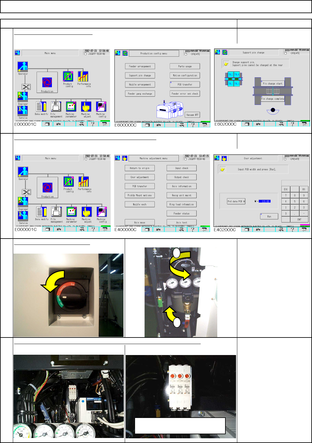
Tools and Specifications Machinery Part Replacement Tools and Specifications Cut the power and air suppl y Remove the support pin plate. 4 3 1 2 Lower the sub plate. Widen the conveyor to maximum. Release the air from th…
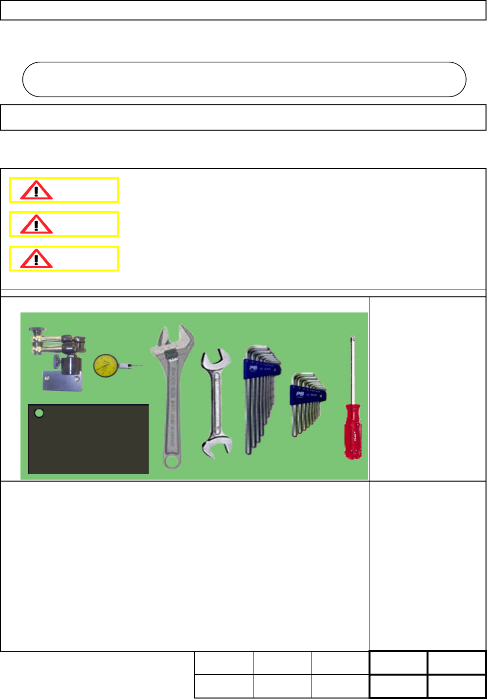
This section describes the procedures for replacing the support plate cylinder.
Phillips screwdriver #2
Allen key 2.5 mm
Allen key 3 mm
Allen key 4 mm
Allen key 5 mm
Wrench 30 mm
Box wrench 30 mm
Dial gauge
Iron plate
Magnetic stand
None
5-2-1 Support Plate Cylinder Replacement
Machinery Part Replacement Board Holder Unit
・Tools
・Jig
30 min. min.
min
.
30
Kgs
.
Removal
Disassembly
A
ssembl
y
Adjustment
Teaching Total Time
Weigh
t
o
f
Part
30 min.
60
Board Holder Unit
5-2
Dange
r
Warning
Caution
EJM8A-E-SMA050201-A01-00
Page 5-2-1-1
Tools and Specifications
Machinery Part Replacement
Tools and Specifications
Cut the power and air suppl
y
Remove the support pin plate.
4
3
1
2
Lower the sub plate. Widen the conveyor to maximum.
Release the air from the perfect block, which is behind the center cover.
Board Holder Unit
Item Remark
Tools and Specifications
Tools and Specifications
1
2
To release the air, press the red
button. (Do not turn it.)
EJM8A-E-SMA050201-A01-00
Page 5-2-1-2
Tools and Specifications
Allen key 3 mm
Screw M4 4 pcs.
5
8
7
Item
6
Phillips screwdriver 2 pcs.
Round cross-head screw
M6 4 pcs.
Tools and Specifications
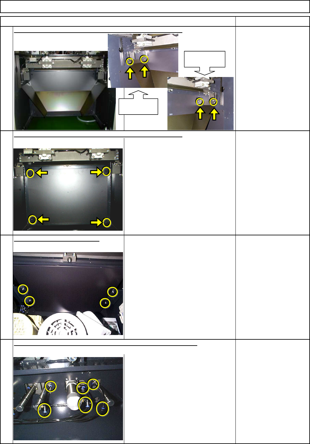
Remove the lower chute from the rear side of the selected stage.
Allen key 4 mm
Screw M5x12mm 4 pcs.
Thick washer 4 pcs.
Remark
Tools and Specifications
Remove the lower cover from the rear side of the selected stage.
Remove the ceiling from the box.
Tools and Specifications
Machinery Part Replacement Board Holder Unit
Remove the air tubs from the support plate and the sub plate cylinders.
Chute holding
section (Left)
Chute holding
section (Right)
EJM8A-E-SMA050201-A01-00
Page 5-2-1-3