CM602all_EJM8AESM_Service Manual.pdf - 第1064页
1. Control System Specifications and Machine Specifications The control system configuration of the DT50S-20 is almost the same as that of the DT40S-20. lComparison of DT Specifications CM602 Direct tray Conventional DT4…
Ji
g
: FM-1924
Level
(
0.02mm/division
)
Actual palette
Actual magazine
(1) Supply section
(2) NG palette
(3) Highest level of upper magazine (1st level)
(4) Highest level of lower magazine (11th level)
(5) Lowest level of lower magazine (20th level)
Note: Check the sensor light in the order
of "blocked" and "emitted." If finding NG
when checking "emitted," re-check
"blocked."
Item
Direct TrayTray
(1) Insert the palettes on all levels.
(2) Move the extension axis to the
checking position.
(3) Check the light is blocked even when
the axis is inched +/-1mm. (5 positions)
1
4
2
X and Y directions: within 0.1mm/m
(1) Remove the palettes from all levels.
(2) Move the extension axis to the
checking position.
(3) Check the light is emitted even when
the axis is inched +/-1mm. (5 positions)
3
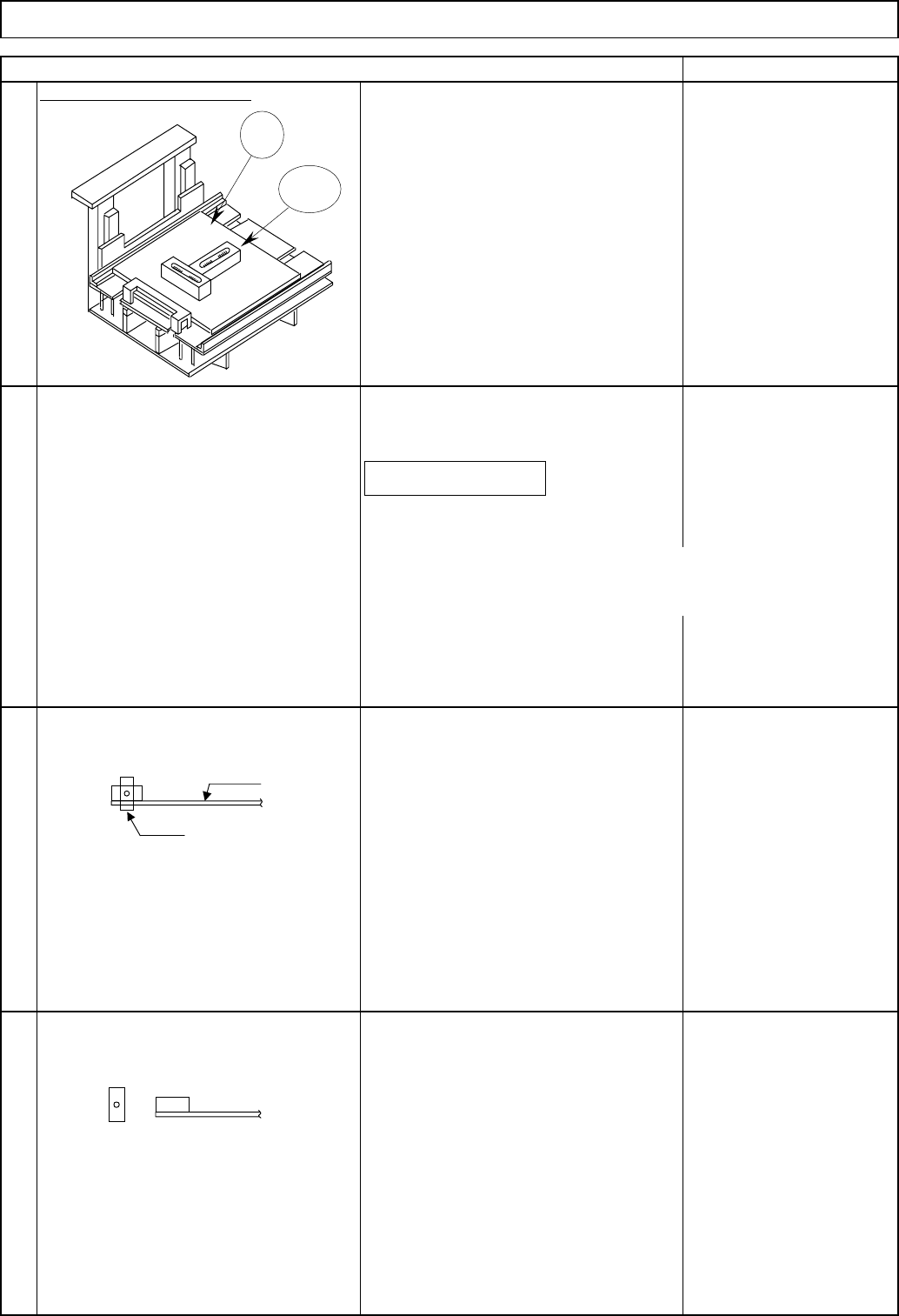
Check the sensor detects correctly.
Remark
Level the extension section
Insert the actual palette.
Level the extension section, using the jig
and the level.
Jig
Level
Check positions
<Check light blocked:
When a palette is inserted>
senso
r
palette
<Check light emitted:
When a palette is removed>
EJM8A-E-SMA070212-A01-00
Page 7-2-12-2

1. Control System Specifications and Machine Specifications
The control system configuration of the DT50S-20 is almost the same as that of the DT40S-20.
lComparison of DT Specifications
CM602 Direct tray Conventional DT40S-20
JEDEC spec.(322.6×135.9×12.19)
Max. 330×230×11
Landscape Portrait
Side of tray Front of tray
20 types 20 types
No. of mounting 2 magazines 2 magazines
No. of levels 10 levels/magazine
←
Pitch 15mm
←
Equipped Equipped
Max. 4 (right of tray) None
Cutter Need to remove
Y-axis
Magnet lengthened. mechanical stoppe
Limi
t
60
mm
out
w
a
r
ds
Pickup position Limit 60mm outwards
Cover 60 mm outwards
Tape-feeder mounting
CM602
changes
Tray Direct Tray
7-2-13 Control System Configuration
Up/down-axis position
Number of component types to mount
Magazine
Tray supply section
Arrangement
Tray size
Tray position
Up/down
Main frame
DT50S-20
Cooling FAN
Breaker
FAN Alarm
MCCB
Power box
CP Servo Driver
DTDR1
TL-AXIS
AC Servo Motor
Brake
TP-AXIS
Tray Connection
Board
ELMMEX
24V
Tray Controller
Sensor Connection Board
× 4
NF24CX EL16C
Power Supply
5V
#0
12V
24V
#1
#2
#3
M
M
M
PH710
PH711
PH716
PH726
LS720
LS721
LS722
LS723
PH724
SW725
PH724T
PH727
VL710
VL711
VL716
SW725LAMP
VL717
DOORSW
Without relay
terminals
Without relay
connectors
NF24CA was
changed
to NF24CB
Servo parameters
changed
Control board
Lift axis
Extension axis
1 - 200V
1 - 200V
1 - 200V
1 - 200V
Servo Driver
DTDR2
AC Servo Motor
Board
12V
12V
12V
12V
EL16C
EL16C
EL16C
PH714
PH715
PH732
PH733
12V
24V
Cart
Up/down axis
Supply
section
EJM8A-E-SMA070213-A01-00
Page 7-2-13-1
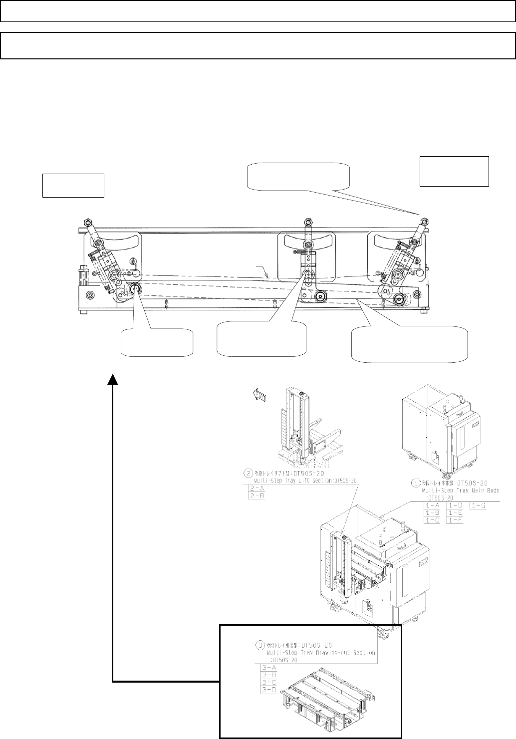
1. New Structure of the Palette Extension Axis
[Structural Characters]
The palette-extension axis is driven by the cam-groove lever shown below so that
the palette-axis structure makes up for the shortage of the stroke amount.
7-2-14 New Structure of the Palette Extension Axis
Direct TrayTray
Cam groove (shown
by dotted line)
Cam follower
Magazine
TP-extension
side
Lever rotation
center
Palette-holding
lever
LM line
EJM8A-E-SMA070214-A01-00
Page 7-2-14-1