CM602all_EJM8AESM_Service Manual.pdf - 第362页
Tools Jigs 5-1-9 X-axis Linear Rail Replacement Main Body Machine Part Replacement This section describes the procedures for replacing the X-axis linear rails. Total Time Part Weight 10 Assembly/Adjustment Removal/Disass…
13
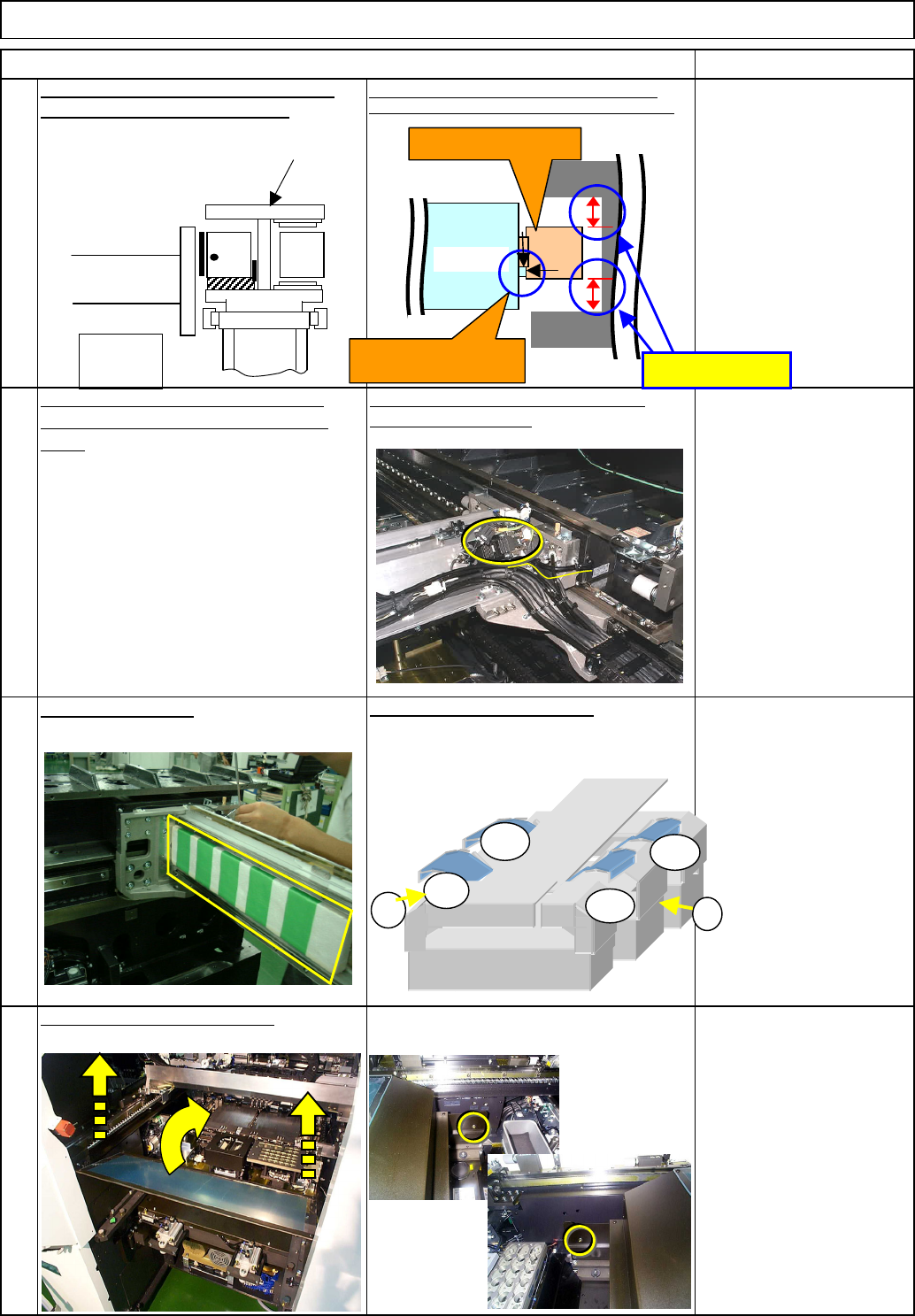
After assembly, check the
gap between the frame
and the secondary part.
Gap: 15 - 15.5 mm
Item Remarks
14
Referring to "Y-axis Secondary-Part
Replacement," mount the secondary
parts.
Secure the cables with a cable tie, and
connect the connector.
Put the feeder cover back on.
Machine Part Replacement
15
Remove the cover.
Put the side covers back on.
Wrench 3 mm
Screw M4 (Special) 2 pcs.
16
Main Body
Holding the handle of the Y-axis primary-
part-slide stand, pull the stand out.
Pressing the primary part against the machined side,
tighten the upper bolts and then lower one. (See below.)
Stage A
Beam
A
F
BR
A
BF
1
2
Y-axis primary part
15 - 15.5 mm
X-axis
Press the part against the
machined side.
Center frame
When seen from operator
EJM8A-E-SMA050108-A01-00
Page 5-1-8-5
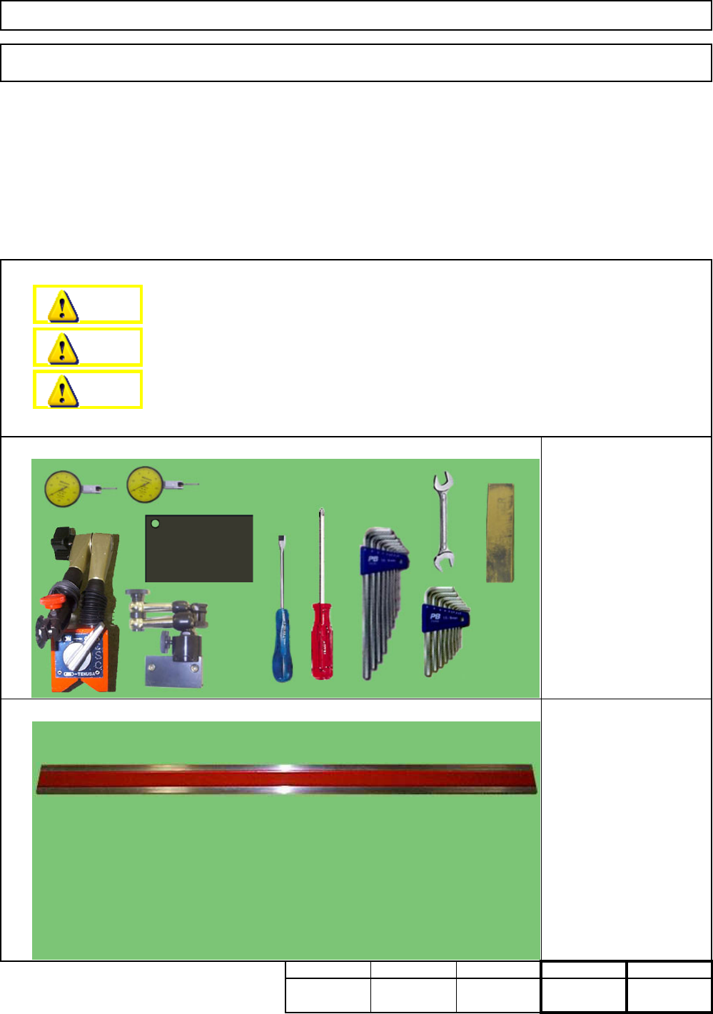
Tools
Jigs
5-1-9 X-axis Linear Rail Replacement
Main BodyMachine Part Replacement
This section describes the procedures for replacing the X-axis linear rails.
Total Time Part Weight
10
Assembly/AdjustmentRemoval/Disassembly
120
Straight edge 1500 mm
Block gauge 35 mm
Block gauge 85 mm
Min.
6040
Phillips screwdriver #2
Slotted screwdriver #1
Allen key 3 mm
Allen key 4 mm
Wrench 7 mm
Magnetic stand
Dial gauge
Iron plate
Oil stone
Cloth
Teaching
Min. Min. kgs.
220
Min.
Dange
r
Warning
Caution
EJM8A-E-SMA050109-A01-00
Page 5-1-9-1
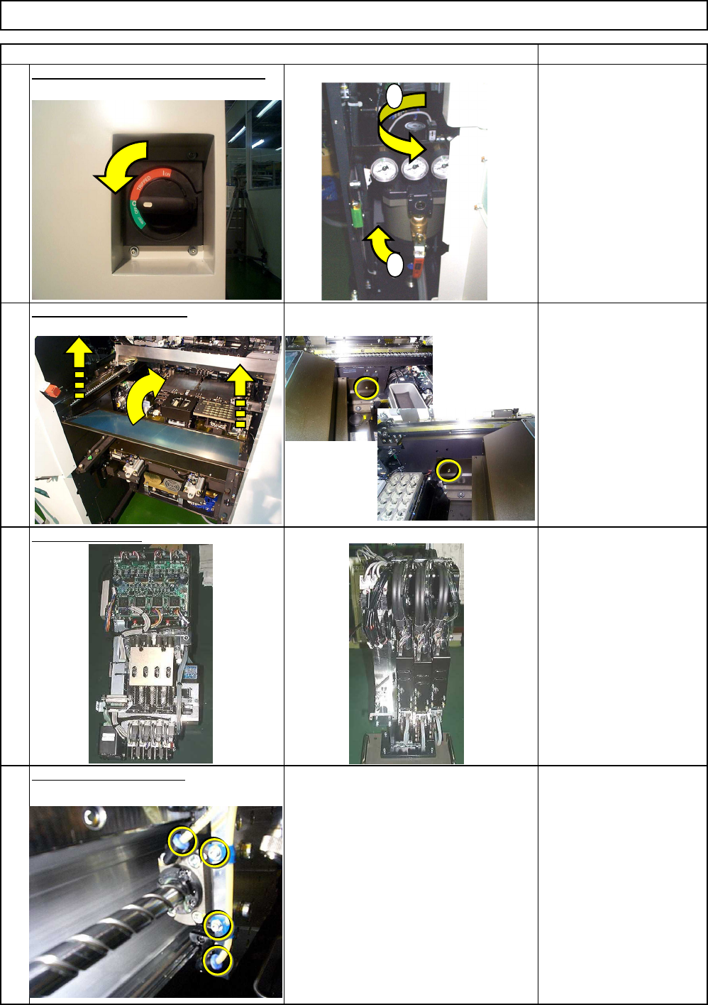
For High-Speed Head, see
Section 5-3-1
"Transfer Head Assembly
Replacement."
For Multi-Purpose Head,
see Section 5-5-2
"Replacing a Set of Head
Units."
Remove the grease hose.
3
4
Allen key 3 mm
Screw M4 4 pcs.
2
1
項目(ITEM)
Remove the feeder cover
.
Machine Part Replacement Main Body
Remove the head.
Phillips screwdriver #2
Screw M4 2 pcs.
備考(REMARK)
Switch off the power and the air supply.
1
2
EJM8A-E-SMA050109-A01-00
Page 5-1-9-2