CM602all_EJM8AESM_Service Manual.pdf - 第348页
13 Put the feeder cover back on. Item Remarks Machine Part Replacement Main Body EJM8A-E-SMA050106-A01-00 Page 5-1-6-5
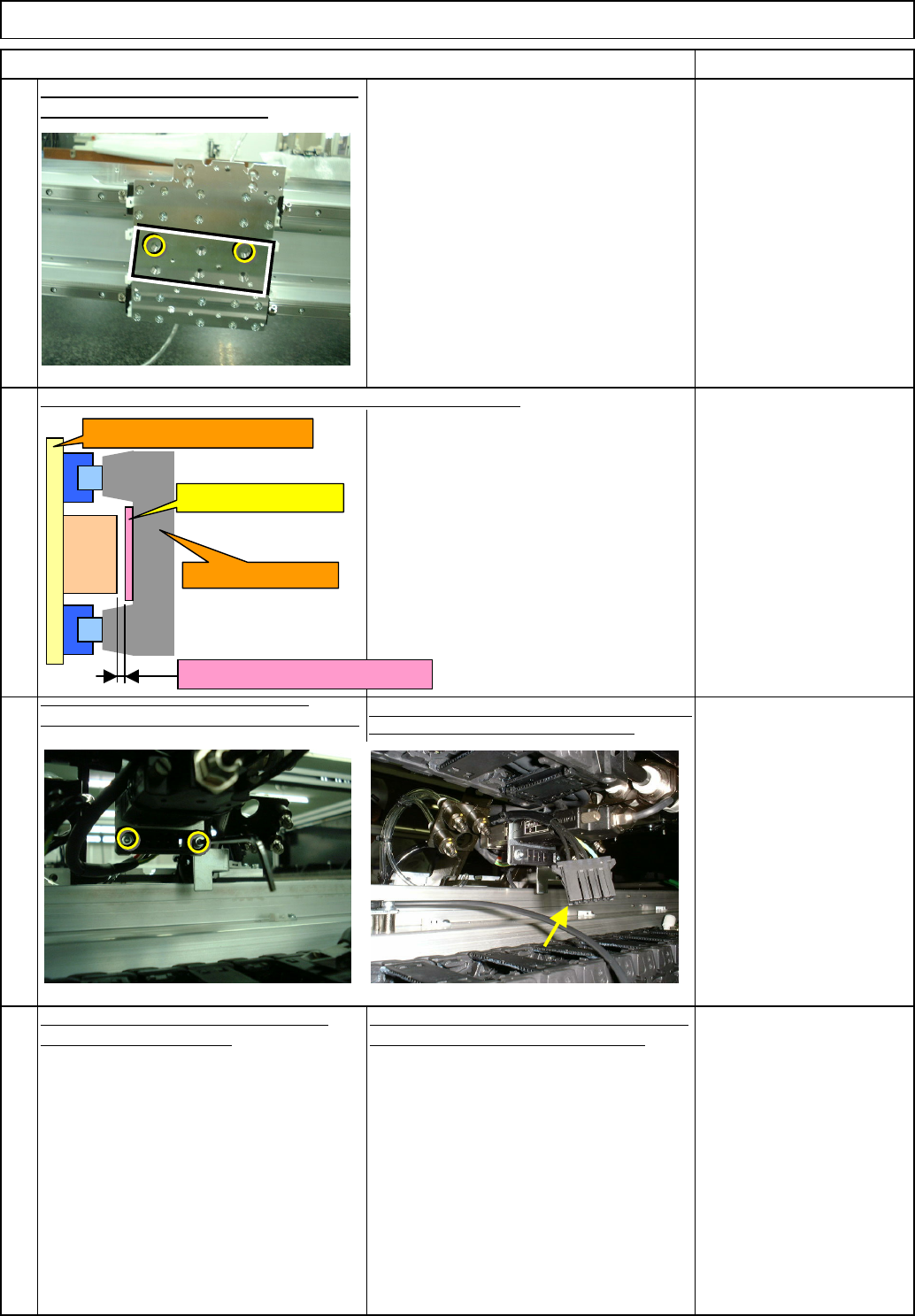
Check the gap between the primary and the secondary parts.
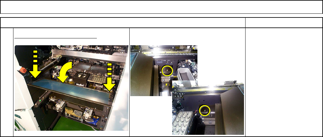
Tighten
the
secondary
-
part
-
connector
holding bolts. Secure the cables with a cable
tie
Connect the connector connecting the secondary part
near the X-axis cable bearer to the machine.
Put the head back on, referring to "Head
Replacement Procedures."
10
11
12
Check the gap with a non-
magnetic material.
Gap: 0.3 mm
Machine Part Replacement
9
Item
Main Body
Remarks
Remove the hollow-set screws. Put the bolts
and tighten them. Bolt x 2 pcs.
Put the secondary parts back on, referring to
"X-axis Secondary-Part Replacement."
Secondary part
Gap should be 0.3 mm.
X-axis beam
Head installing plate
Primary
part
EJM8A-E-SMA050106-A01-00
Page 5-1-6-4
13
Put the feeder cover back on.
Item Remarks
Machine Part Replacement Main Body
EJM8A-E-SMA050106-A01-00
Page 5-1-6-5
I Since this adjustment requires releasing the safety cover switch, only those who are
authorized to release it based on the Document "Key Switch/Key Disk Receipt
Confirmation and Safety Precautions" are permitted to perform this adjustment.
Main Body
5-1-7 Y-axis Secondary-Part Replacement
Machinery Part Replacement
Min.60 Min.
kg
Assembly/Adjustment
Teaching
120
Min.60 Min.
• This section describes the procedures for replacing the Y-axis secondary-part.
Total Time Part Weight
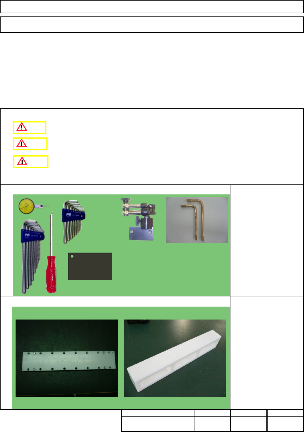
Cover jigs
Y-axis secondary-part
installing jig
Tools
Jig
Phillips screwdriver #2
Allen keys 3 - 5mm
Magnetic stand
Stand-mounting iron plate
Dial gauge
Short wrench
Non-magnetic Allen key
Removal/Disassembly
Caution
Danger
Warning
Non-magnetic Allen key (Straight)
Should be short-processed.)
Picture: Manufacturer: TRUSCO
NAKAYAMA
Flame-proof tool series
Model: BHX-4, BHX-5 (Size M4 and M5)
EJM8A-E-SMA050107-A01-00 Page 5-1-7-1