CM602all_EJM8AESM_Service Manual.pdf - 第606页
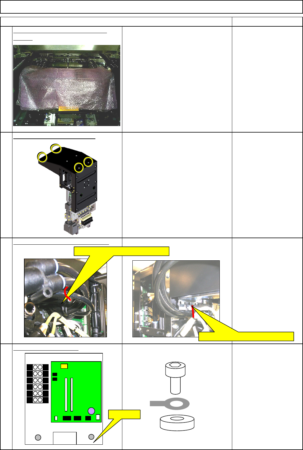
Machinery Part Replacement Remark Item 12-Nozzle Head Unit Remove the holding bolts. Screw M4 x 8L 2 pcs. Thick washer Remove the connectors. Remove the tube joints. Remove the camera connector. 12 10 11 9 C12-M(st,No) ⇒…
Machinery Part Replacement
Remark
Item
12-Nozzle Head Unit
Put bubble wrap on the line camera
sensor. To prevent the head from falling down. Bubble wrap
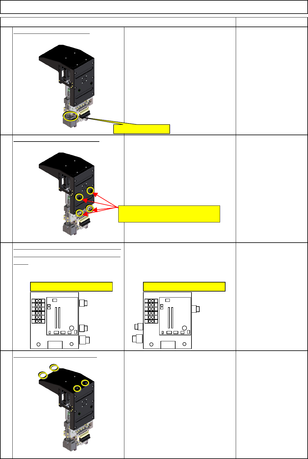
Remove the upper head cover.
Phillips screwdriver #2
M4 truss 4 pcs.
Remove the tube-securing cable tie.
Nippers
Remove the earth cable.
Thick washer
Screw M4 x 8L 1 pc.
8
7
6
5
Remove the AF and BR cable ties.
Remove the AR and BF cable ties.
FG⇒Earth
EJM8A-E-SMA051001-A01-00
Page 5-10-1-3
Machinery Part Replacement
Remark
Item
12-Nozzle Head Unit
Remove the holding bolts.
Screw M4 x 8L 2 pcs.
Thick washer
Remove the connectors.
Remove the tube joints.
Remove the camera connector.
12
10
11
9
C12-M(st,No)⇒CN12
C8-M(st,No)⇒CN8
C9-M(st,No)⇒CN9
CN2-M(st,No)⇒CN2
CN11-M(st,No)⇒CN11
C1-M(st,No)⇒CN1
Remove the M4×8L screws and the washers.
Positions of AF and BR joints Positions of AR and BF joints
Vacuum release joints
Vacuum joints
Head camera connector
EJM8A-E-SMA051001-A01-00
Page 5-10-1-4
Machinery Part Replacement
Remark
Item
12-Nozzle Head Unit
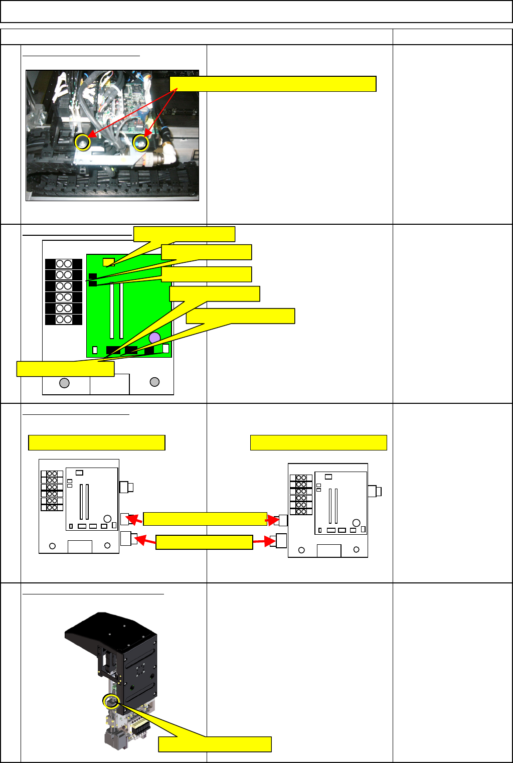
Remove the LED connector.
Remove the head-holding bolts.
Allen key 5 mm
Pipe
M6 screw 4 pcs.
After the screws have
been removed, hold the
head by hand.
(Otherwise, it can fall
down.)
Check the positions of the air tube joints
of the new head and the head-mounting
table.
* Positions of the joints when seen from
the operator's side:
AF and BR: Right
AR and BR: Left
Remove the upper head cover.
Phillips screwdriver #2
M4 truss 4 pcs.
13
14
15
16
LED light connector
Positions of AF and BR joints Positions of AR and BF joints
Insert an Allen key through these
positions into the head-holding bolts.
EJM8A-E-SMA051001-A01-00
Page 5-10-1-5