CM602all_EJM8AESM_Service Manual.pdf - 第273页
Maintenance Adjustment Light Transfer-Head Assembly (3 nozzles) This section describes the procedures for carrying out the XY plane calibration. ・ Tools None ・ Jig FM-1045 XY plane calibration jig 510 mm x 460 mm Remove …
Maintenance Adjustment Light Transfer-Head Assembly (3 nozzles)
Remarks
Item
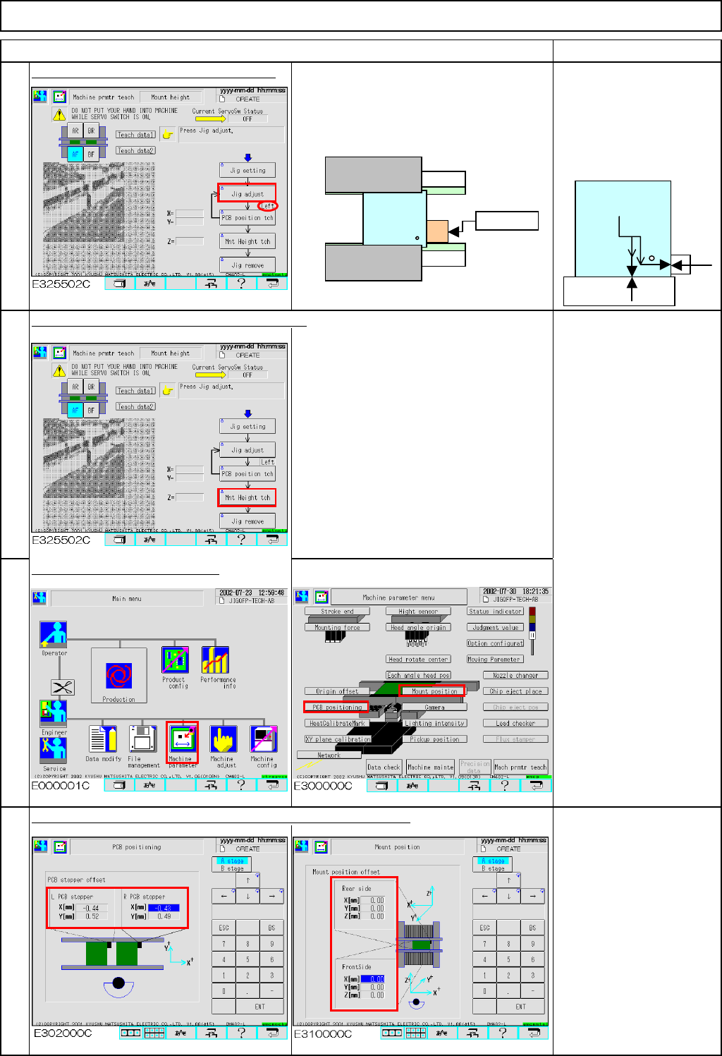
Press the "Unlock" key and [Jig adjust].
Check that "Left" is selected for the jig
position. Firmly press the jig against the
board-clamp-holding guide and the
stopper.
Take care with the
orientation of the jig;
the hole on the jig should
face the stopper and the
fixed guide.
Press the "Unlock" key and [Mnt Height tch].
While the nozzle ascending and
descending above the jig, the vacuum
pressure is measured and the offset is
set automatically.
Only the mounting height is taught on the
rear side.
Check the data after teaching.
The offsets are entered automatically into the screens below:
Offset range:
PCB stopper:
X: -2.0 mm to +2.0 mm
Y: -2.0 mm to +2.0 mm
Mount position offset:
X: -1.0 mm to +1.0 mm
Y: -1.0 mm to +1.0 mm
Z: -1.0 mm to +1.0 mm
18
19
20
17
No gap should
be created.
ストッパー
固定側
Stopper
Fixed guide
EJM8A-E-SMA040305-A01-00
Page 4-3-5-6
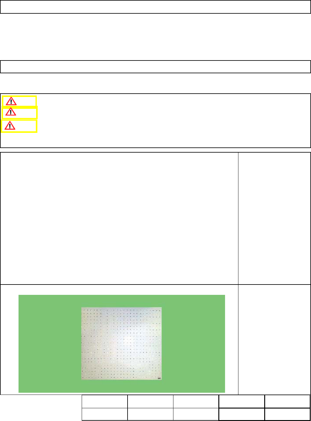
Maintenance Adjustment Light Transfer-Head Assembly (3 nozzles)
This section describes the procedures for carrying out the XY plane calibration.
・Tools
None
・Jig
FM-1045
XY plane calibration jig
510 mm x 460 mm
Remove dirt from the
recognition side of the jig
with soft cloth.
4-3-6 XY Plane Calibration
Remove the support pins beforehand.
Handle the jig with care since it is made of glass.
This calibration should be carried out on the operator's side; it cannot
Caution
Dange
r
Warning
Assembly
Adjustment
min.
Teaching
20min.
Total Time Weight of
Part
Removal
Disassembly
min.
20min.
kgs
EJM8A-E-SMA040306-A01-00
Page 4-3-6-1
Maintenance Adjustment Light Transfer-Head Assembly (3 nozzles)
Remarks
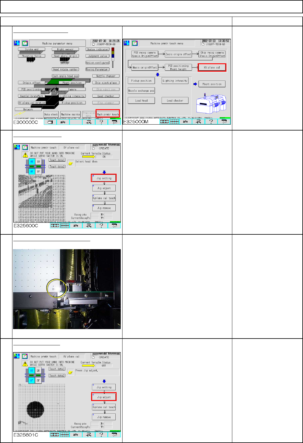
Press [XY plane cal].
Conveyor width is
adjusted to 460 mm
automatically.
Press [Jig setting].
The AF head moves away.
Place the jig on the conveyor.
Place the jig by hand, pressing the
reference-mark corner of the jig against
the fixed conveyor and the board
stopper.
Press [Jig adjust].
The jig is clamped in the Y direction.
(Option)
Check that the jig is
locked once it is clamped
in the Y direction.
3
4
1
2
Item
EJM8A-E-SMA040306-A01-00
Page 4-3-6-2