CM602all_EJM8AESM_Service Manual.pdf - 第956页
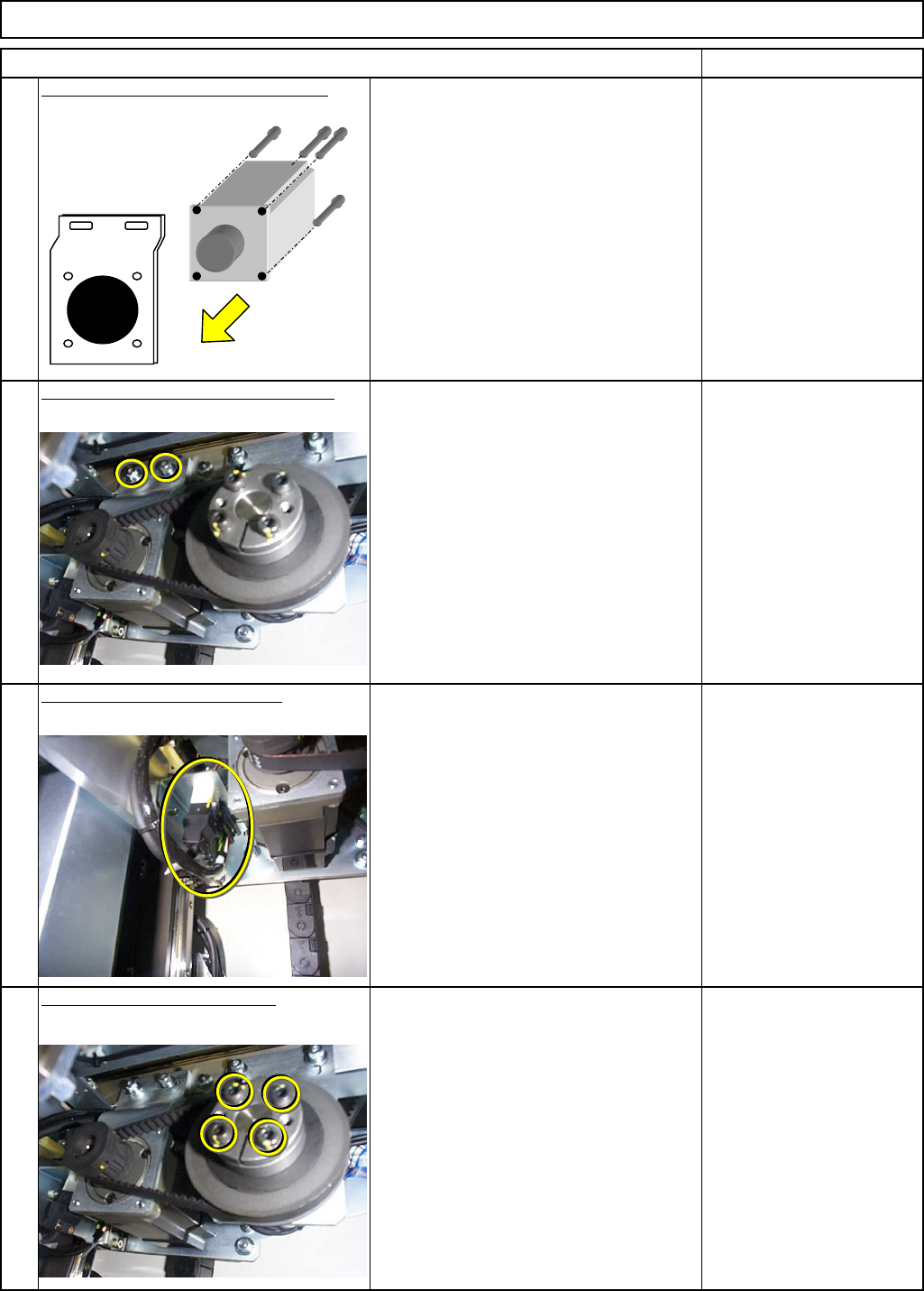
After loosenin g , li g ht hit and remove the lock. Tray Shuttle Tray Loosen the motor power lock. 10 11 12 Allen key 4 mm Screw M5 4 pcs. Connect thte motor connector. Allen key 4 mm Screw M5 2 pcs. Item Remarks Install…
Shuttle Tray
Allen key 4 mm
Screw M5 4 pcs.
6
7
8
aligning it to the D-shaped cut. Tighten it.
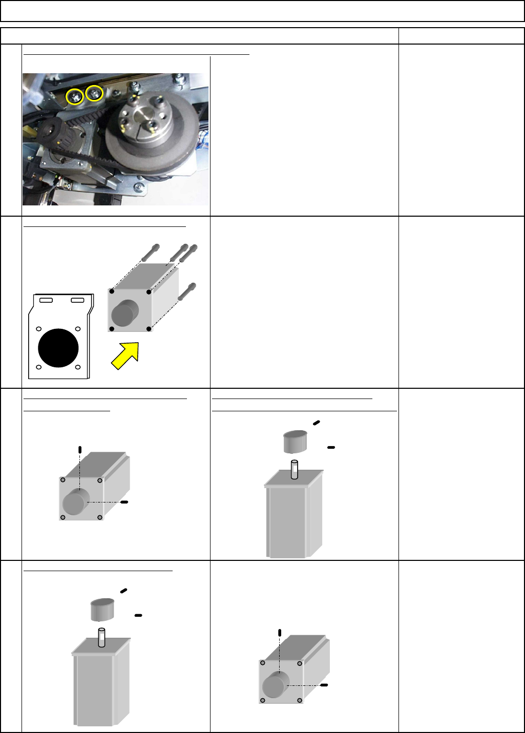
Remove the motor from the bracket.
Allen key 2 mm
Setscrew M3 2 pcs.
Remarks
Tray
5
Item
Allen key 4 mm
Screw M5 2 pcs.
Loosen the motor belt tension. Remove the motor.
Remove the motor pulley setscrews. Fit one setscrew on the motor axis,
Remove the pulley.
Replace the motor. Fit the pulley.
Allen key 2 mm
Setscrew M3 2 pcs.
Pulley remover
EJM8A-E-SMA070113-A01-00
Page 7-1-13-3
After loosenin
g
, li
g
ht hit and remove
the lock.
Tray Shuttle Tray
Loosen the motor power lock.
10
11
12
Allen key 4 mm
Screw M5 4 pcs.
Connect thte motor connector.
Allen key 4 mm
Screw M5 2 pcs.
Item Remarks
Install the motor and tension the belt.
9
Combine the motor with the bracket.
Allen key 4 mm
Screw M5 4 pcs.
EJM8A-E-SMA070113-A01-00
Page 7-1-13-4
Tray Shuttle Tray
Item Remarks
15
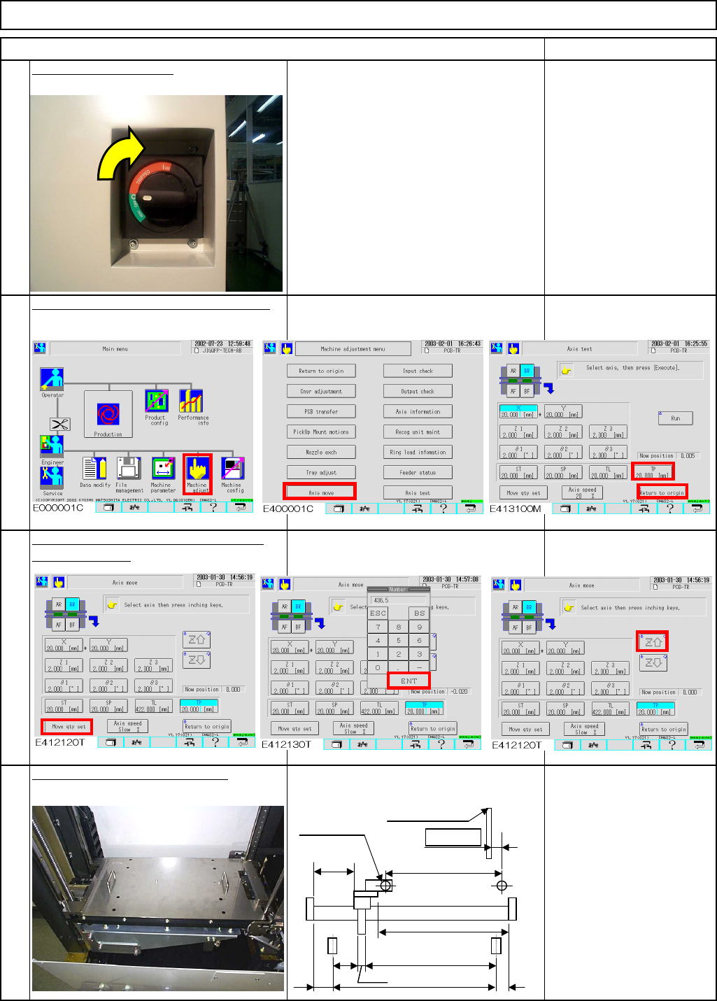
Move the extension axis towards you
Return the extension-axis to the origin.
14
16
Position the bearing with the jig.
Jig: FM-0982
by 436.5 stroke.
13
Power up the machine.
This area should be for
servicemen only because
the cover is open.
A
=436.5st
Origin
E
CD
(454.5)
8
F
B=11.0
Whole shutter
(2)
(73)
436.5
EJM8A-E-SMA070113-A01-00
Page 7-1-13-5