CM602all_EJM8AESM_Service Manual.pdf - 第448页
min. min. min. min. k g . Machinery Part Replacement Li g ht T rans f er- H ea d A ssem bl y (8 -nozz l e type) ・ Jigs Removal/Disassembly 80 40 90 • This section describes the procedures for replacing the Z-axis ball sc…
Machinery Part Replacement
Remarks
L
ight Transfer-Head Assembly (8-nozzle type
)
Item
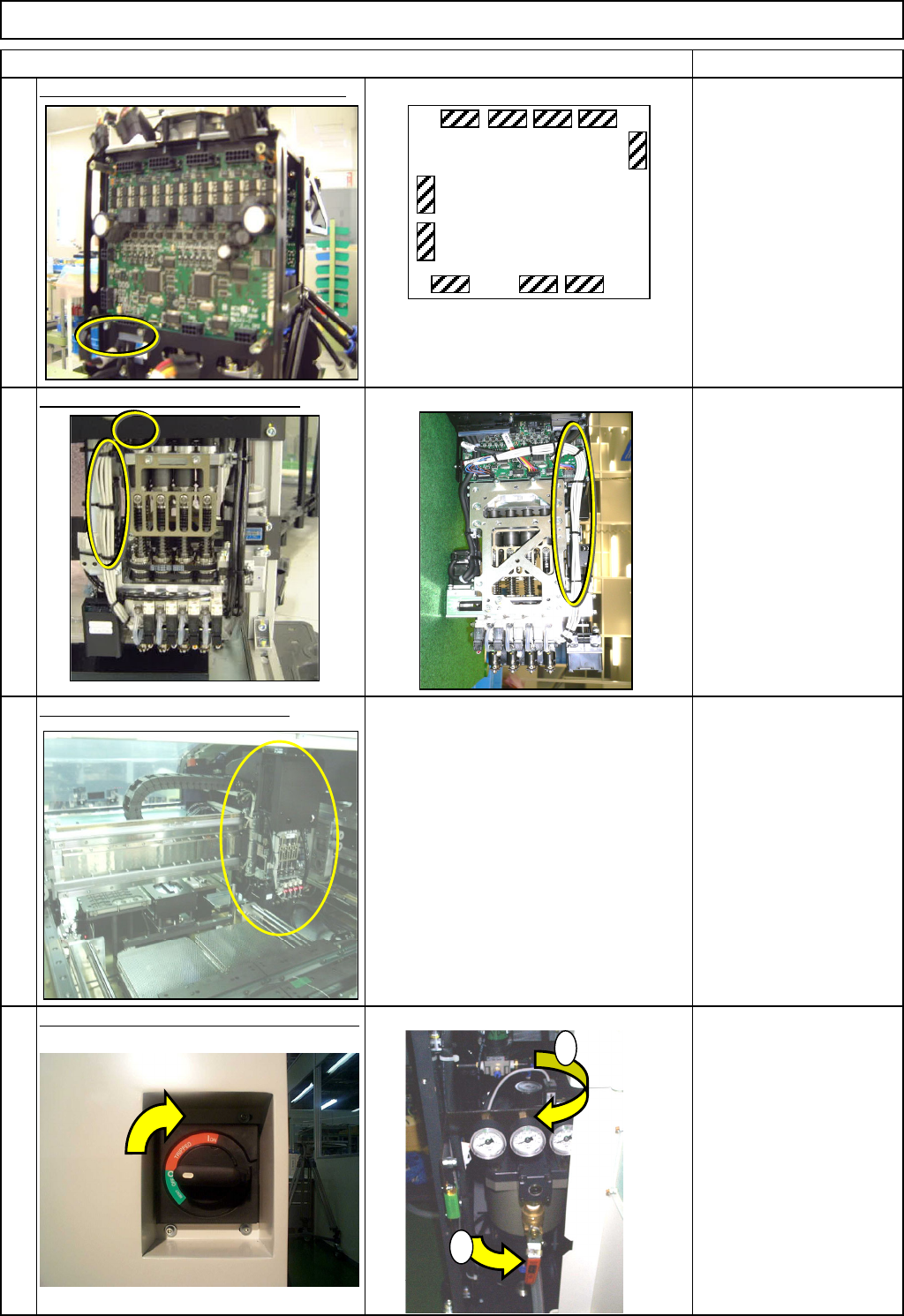
Connect the vacuum sensor connector.
Secure the cables with cable ties. Rear side
Nipper
Cable ties
Put the head assembly back on.
Refer to "Transfer Head Replacement." Section 5-3-1
Switch on the main power and air supply.
15
14
13
16
CN1
CN2
CN3 CN4
CN5
CN12
CN10CN9
CN7
CN6
MC14CX
1
2
The same boards are installed at
the front and the rear side of the
head assembly.
EJM8A-E-SMA050310-A01-00
Page 5-3-10-5
min. min. min. min.
k
g
.
Machinery Part Replacement
Li
g
ht
T
rans
f
er-
H
ea
d
A
ssem
bl
y
(8
-nozz
l
e
type)
・Jigs
Removal/Disassembly
8040 90
• This section describes the procedures for replacing the Z-axis ball screw.
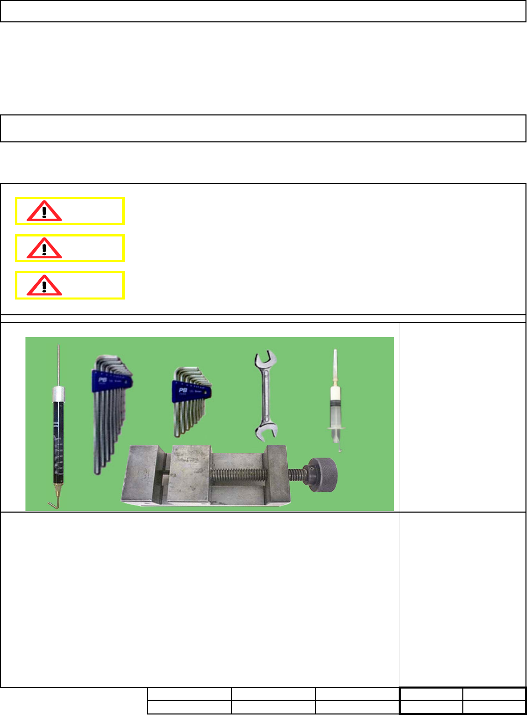
5-3-11 Z-axis Ball Screw Replacement
Allen key 1.5 mm
Allen key 2 mm
Allen key 3 mm
Wrench 17 mm
Spring balance
BARRIERTA IEL/V
Vise
None
Part Weight
Total
210
Teaching
--
・Tools
Assembly/Adjustment
Dange
r
Warning
Caution
EJM8A-E-SMA050311-A01-00
Page 5-3-11-1
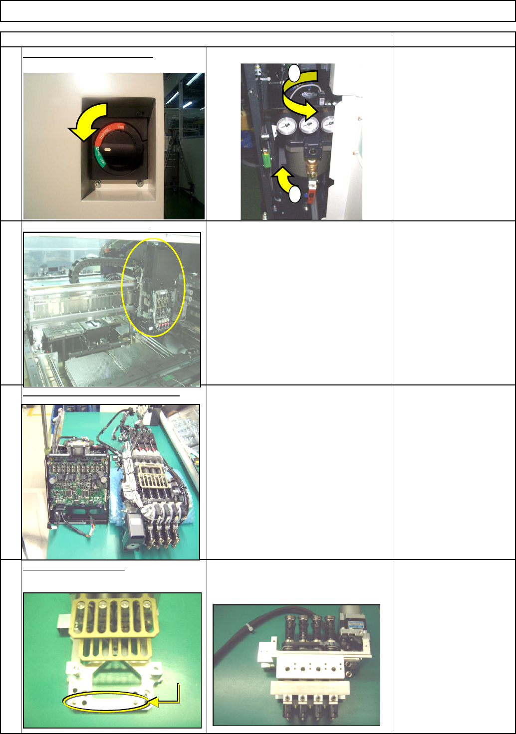
See "Theta Unit Removable"
1
Item Remarks
Cut the power and air supply.
3
4
Remove the theta unit.
2
Machinery Part Replacement
Li
g
ht
T
rans
f
er-
H
ea
d
A
ssem
bl
y
(8
-nozz
l
e
type)
Allen key 3 mm
Screw M4 x 4
Section 5-3-14
Remove the head assembly.
Separate the Z unit from the board.
See "Transfer Head Assembly
Replacement."
See "Separating the Z-Unit from the
Board."
Section 5-3-1
1
2
Dowel pin
EJM8A-E-SMA050311-A01-00
Page 5-3-11-2