CM602all_EJM8AESM_Service Manual.pdf - 第556页
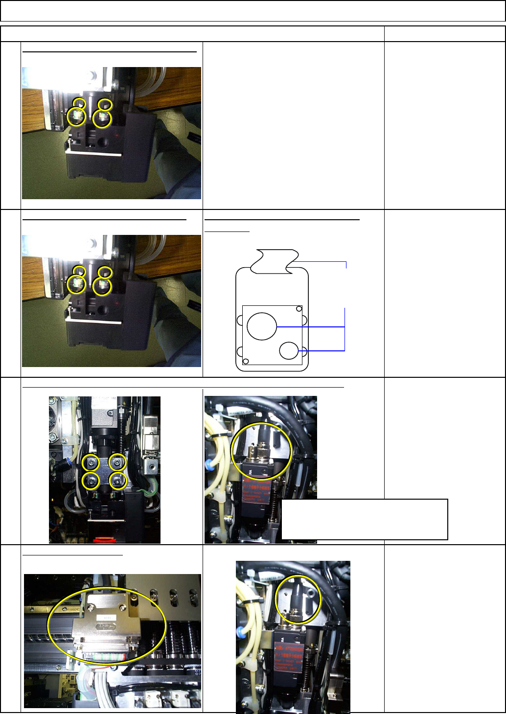
Top vie w Tools and Specifications Remove the LED lamp from the camera. Take care with the orientation of the Fit the new LED lamp into the camera. 6 5 Machinery Part Replacement Head Camera Unit Item Remarks Tools and S…
Be careful not to let the camera fall.
Tools and Specifications
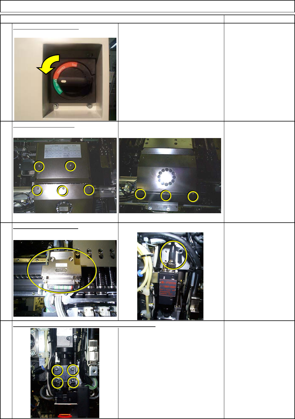
Remove the camera holding screws, holding the camera.
2
1
4
3
Item Remarks
Allen key 3 mm
Screw M4 4 pcs.
Remove the head cover.
Switch off the main power.
Tools and Specifications
Tools and Specifications
Phillips screwdriver #1
Connector screw
Disconnect the connector.
Tools and Specifications
Phillips screwdriver #1
Phillips screwdriver #2
Screw M3 8 pcs.
M4 4 pcs.
Machinery Part Replacement Head Camera Unit
EJM8A-E-SMA050603-A01-00
Page 5-6-3-2
Top vie
w
Tools and Specifications
Remove the LED lamp from the camera.
Take care with the orientation of the Fit the new LED lamp into the camera.
6
5
Machinery Part Replacement Head Camera Unit
Item Remarks
Tools and Specifications
connector.
Connect the connector.
Tools and Specifications
8
7
Tools and Specifications
Install the camera. Lightly tighten the screws so that the camera will not fall.
Camera connector
LED cable
Take care with the orientation of the
camera. (Check the connector
position.)
EJM8A-E-SMA050603-A01-00
Page 5-6-3-3
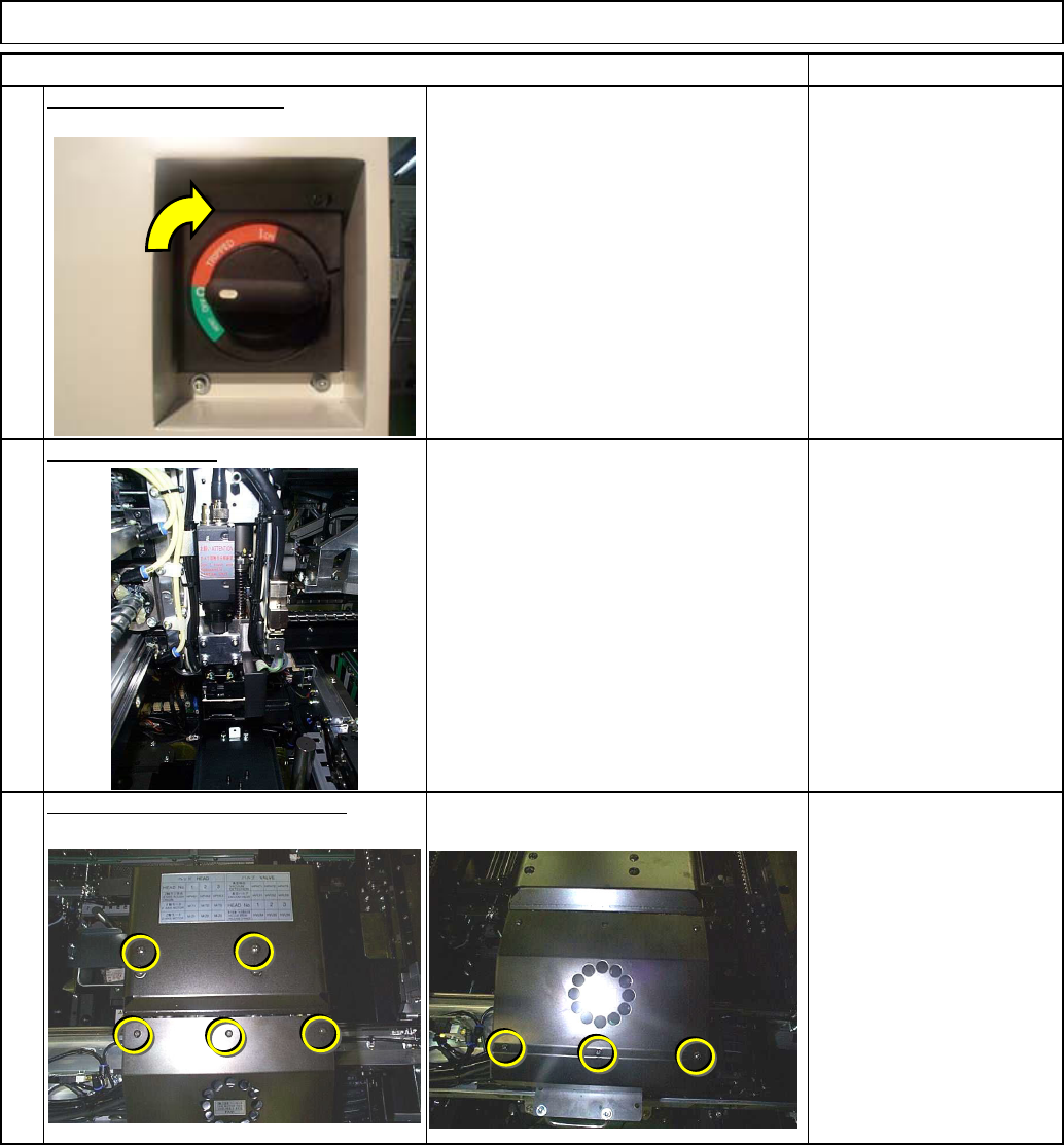
Refer to "Head Camera Adjustment
--- Focus and Theta --."
Machinery Part Replacement Head Camera Unit
Section 4-1-2
Tools and Specifications
Item Remarks
9
Switch on the main power.
Tools and Specifications
Adjust the camera.
Tools and Specifications
Phillips screwdriver #1
Phillips screwdriver #2
Screw M3 8 pcs.
M4 4 pcs.
10
11
Put B214the head cover back on.
EJM8A-E-SMA050603-A01-00
Page 5-6-3-4