CM602all_EJM8AESM_Service Manual.pdf - 第665页
Machinery Part Replacement This section describes the procedures for focusing the head camera and positioning it in the theta direction. ・ Tools Phillips screwdriver #2 Allen key 1.5 mm Allen key 3.0 mm ・ Jig Head camera…
Machinery Part Replacement
Remark
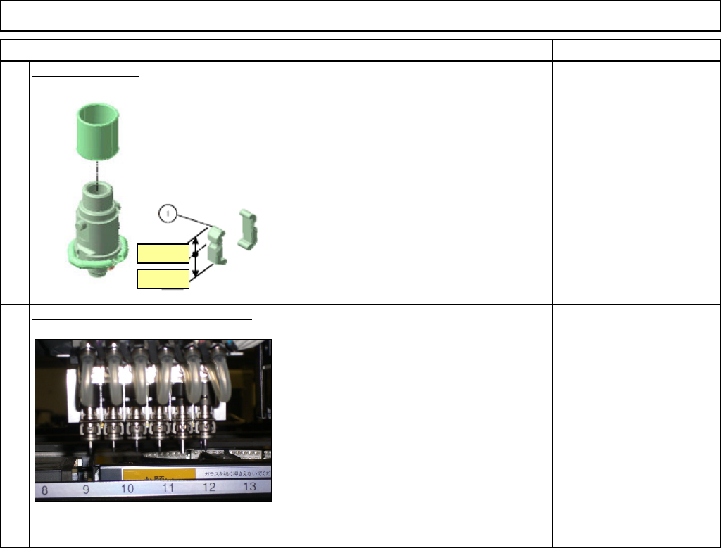
12-Nozzle Head Unit
Item
Replace the arm.
Be careful not to position the arm upside
down.
Fit the spring and the nozzle holder
5
4
Narrow
Wide
EJM8A-E-SMA051010-A01-00
Page 5-10-10-3
Machinery Part Replacement
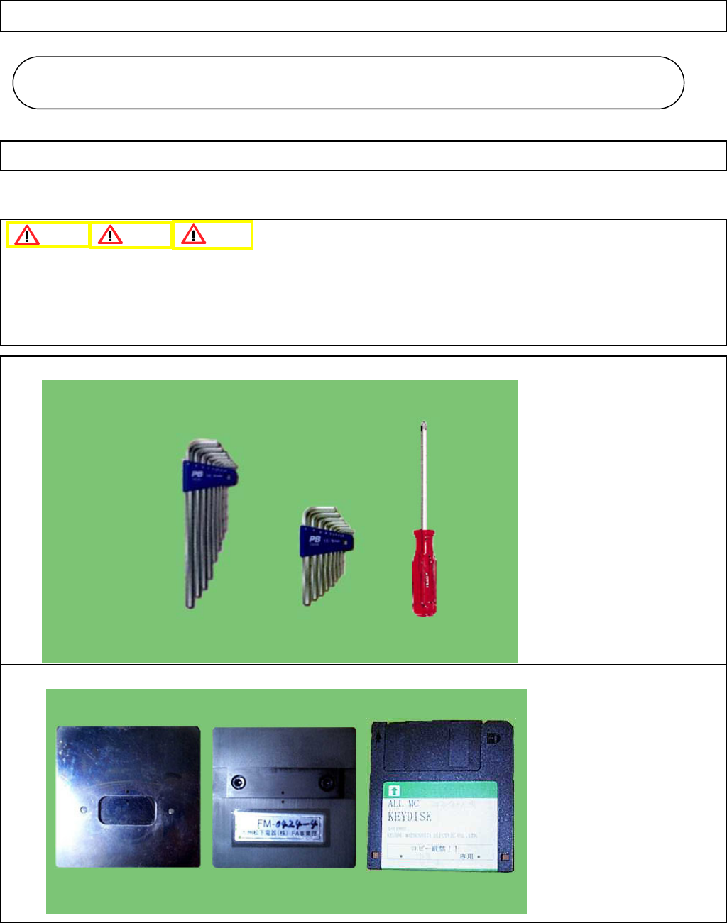
This section describes the procedures for focusing the head camera and positioning it in the theta direction.
・Tools
Phillips screwdriver #2
Allen key 1.5 mm
Allen key 3.0 mm
・Jig
Head camera focusing jig
Key disk
5-11-1 Head Camera Adjustment --- Focus and θ
1. Since this adjustment requires parameter changes using the key disk, only those who are authorized to use
the key disk based on the Document "Key Switch/Key Disk Receipt Confirmation and Safety Precautions" are
permitted to perform this adjustment.
2. Remove the support pins beforehand.
12-Nozzle Head Teaching
Caution
Dange
r
Warning
12-Nozzle Head Teachin
g
5-11
EJM8A-E-SMA051101-A01-00
Page 5-11-1-1
Machinery Part Replacement
Remarks
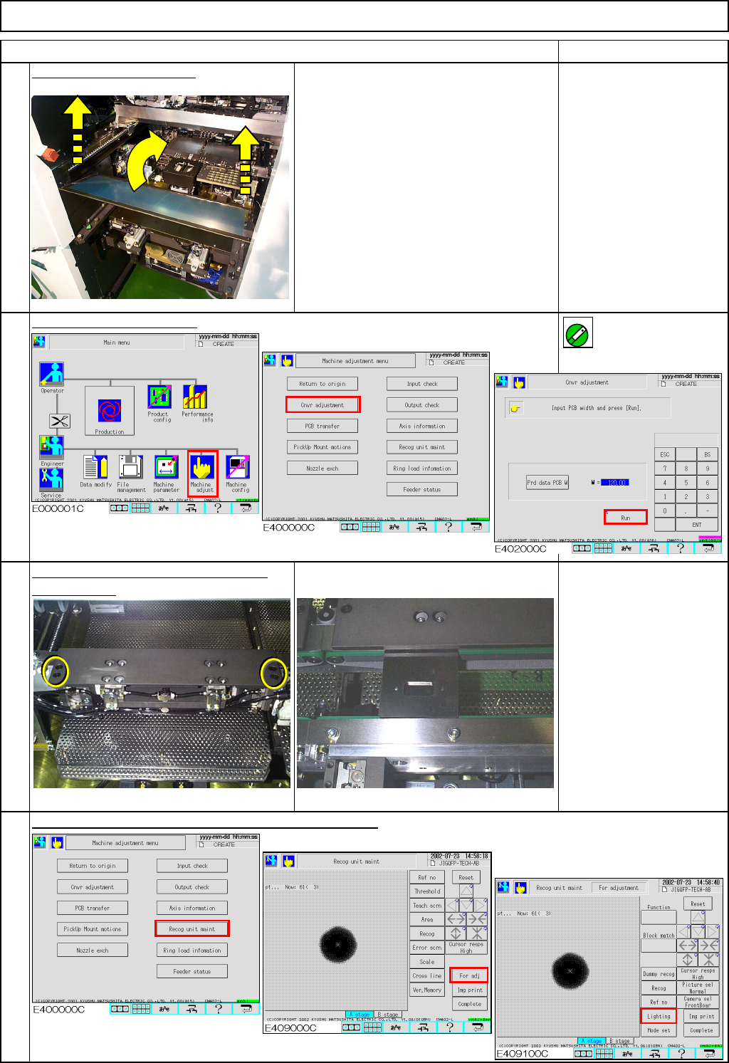
Remove the feeder cover.
Phillips screwdriver #2
Screw M4 2 pcs.
Adjust the conveyor width.
Enter 50 into the [W] box.
Remove the fixed and the movable Z
Place the
j
i
g
on the conve
y
or.
clamp plates.
Head camera focusing jig
Allen key 3 mm
Screw M4 4 pcs.
"Recognition unit maintenance For adjustment" screen
Key disk
Refer to "Key Switch/Key
Disk Receipt Confirmation
and Safety Precautions."
3
4
1
Item
2
12-Nozzle Head Teaching
ON
EJM8A-E-SMA051101-A01-00
Page 5-11-1-2